
Understanding the Multimeter
Understanding the Multimeter
A multimeter is an essential tool for both professional electricians and DIY enthusiasts, as it allows for the measurement of various electrical properties in an accurate and efficient manner. This versatile device can measure voltage, current, and resistance, making it indispensable for troubleshooting electrical circuits and components.
When using a multimeter, it's important to understand its basic components. The display screen provides readings for the measured quantities, while the selection dial allows users to choose the type of measurement they want to perform. The two probes, typically color-coded red and black, are used to make contact with the circuit or component being tested.
The multimeter operates in different modes to measure specific electrical properties. The voltage mode is used to measure the potential difference between two points in a circuit, while the current mode measures the flow of electric charge. The resistance mode determines the resistance of a component, and the continuity mode checks if a circuit is complete.
Additionally, it's crucial to comprehend the concept of range when using a multimeter. Each measurement mode has multiple ranges to accommodate a wide range of values. Selecting the appropriate range ensures accurate readings and prevents damage to the multimeter.
By understanding the fundamental components, modes, and ranges of a multimeter, users can effectively utilize this tool to diagnose electrical issues and ensure the proper functioning of circuits and components.
Setting Up the Multimeter for Testing
Before conducting tests with a multimeter, it’s crucial to properly set it up to ensure accurate measurements. The following steps outline the process of preparing the multimeter for testing:
- Power Off: When beginning the setup process, ensure that the circuit or device being tested is powered off to prevent electrical hazards.
- Select the Measurement Mode: Turn the selection dial to choose the appropriate measurement mode based on the property being tested, such as voltage, current, resistance, or continuity.
- Choose the Range: Select the suitable range for the expected value of the property being measured. Start with the highest range and gradually decrease it for more precise readings.
- Insert the Probes: Insert the red probe into the terminal labeled for positive measurements and the black probe into the terminal designated for negative measurements.
- Set the Function: If the multimeter has additional functions, such as diode or capacitance testing, select the appropriate function on the dial.
- Adjust the Display: Some multimeters have adjustable display settings, such as backlighting or contrast. Set these options according to the testing environment for better visibility of readings.
- Verify Connections: Double-check that the probes are securely connected to the circuit or component being tested to ensure accurate results.
By following these steps, users can effectively set up the multimeter for testing, enabling precise and reliable measurements of electrical properties.
Testing for Continuity
Continuity testing is a vital function of a multimeter, as it allows users to determine if a circuit is complete and free of breaks or interruptions. This test is particularly useful when troubleshooting wiring, fuses, switches, and electrical connections. The following steps outline the process of conducting a continuity test using a multimeter:
- Power Off: Ensure that the circuit or equipment under test is not energized to prevent electrical accidents.
- Select Continuity Mode: Turn the dial to the continuity mode, often denoted by a sound wave symbol or the word “CONT.”
- Probe Placement: Place the red and black probes on each end of the circuit or connection being tested. The color coding is not critical for continuity testing.
- Interpret the Reading: If the circuit is continuous (no breaks), the multimeter will emit a sound, indicating a closed circuit. Additionally, the display may show a numerical value close to zero, indicating very low resistance.
- Inspect Specific Components: Continuity testing can also be used to check individual components, such as fuses and switches, to ensure they are functioning as intended.
- Identify Breaks: If the multimeter does not emit a sound or shows a high resistance value, it indicates an open circuit, suggesting a break or interruption in the tested component or wiring.
By following these steps, users can effectively perform continuity tests using a multimeter, enabling them to identify open or closed circuits, troubleshoot electrical issues, and ensure the integrity of connections and components.
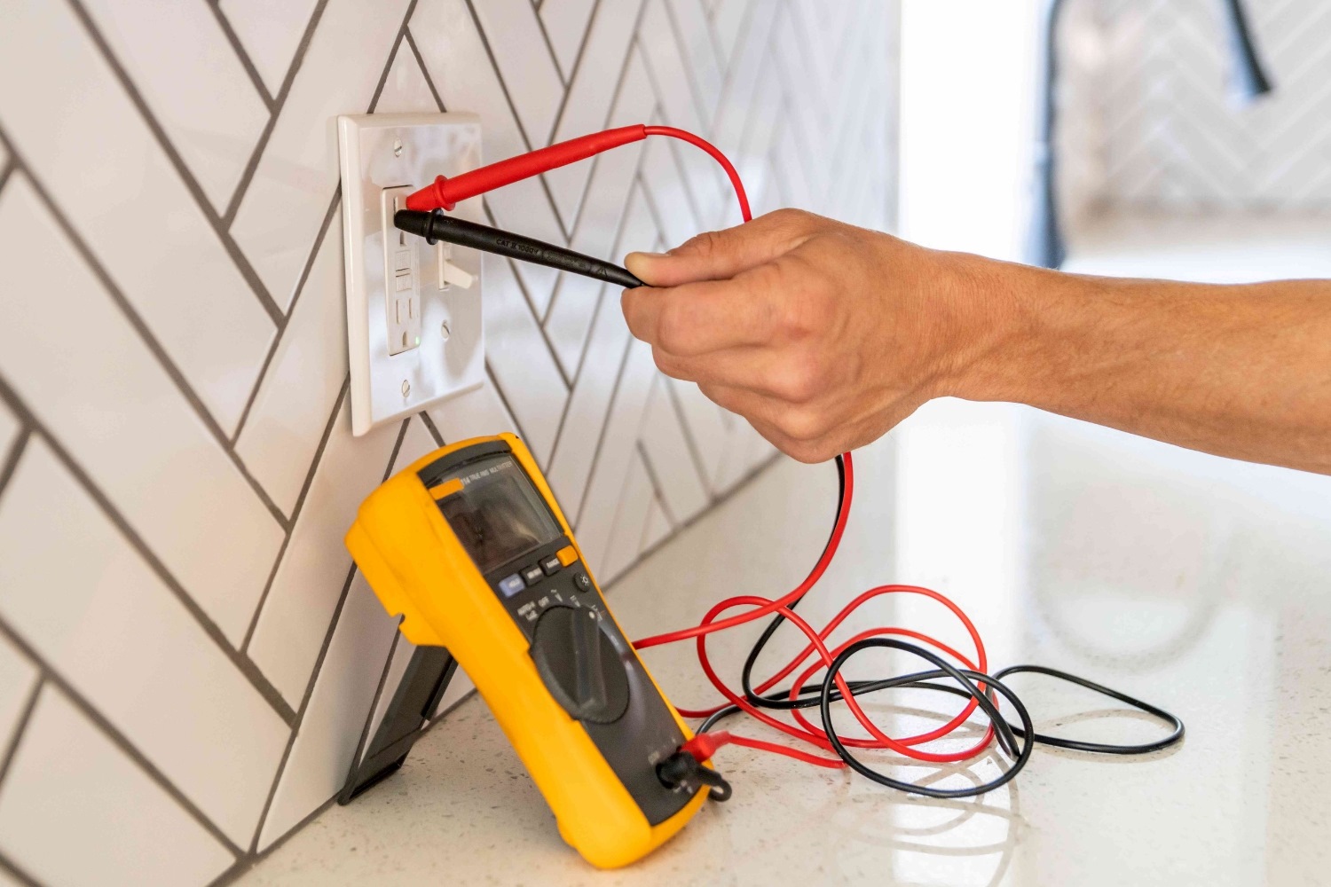
Testing for Voltage
Measuring voltage is a fundamental function of a multimeter and is essential for assessing the electrical potential difference between two points in a circuit. This test is commonly used to diagnose power supply issues, check battery voltage, and troubleshoot electrical systems. The following steps outline the process of testing for voltage using a multimeter:
- Select Voltage Mode: Turn the dial to the voltage mode, typically denoted by the symbol “V” with a straight line or a series of wavy lines, representing alternating current (AC) voltage.
- Choose the Range: Select the appropriate voltage range on the multimeter based on the expected voltage level. Start with a higher range and adjust as needed for accurate measurements.
- Probe Placement: Insert the red probe into the terminal for positive voltage measurements and the black probe into the terminal for negative measurements.
- Connect to the Circuit: Place the probes at the points in the circuit where the voltage is to be measured. Ensure a secure connection to obtain an accurate reading.
- Read the Display: The multimeter will display the measured voltage in volts on the screen. If the voltage is within the selected range, the reading will be accurate. If the value exceeds the selected range, adjust to a higher range to avoid overloading the multimeter.
- Interpret the Results: Analyze the voltage reading to assess the electrical condition of the circuit. Abnormal readings may indicate issues such as voltage drops, irregular power supply, or circuit malfunctions.
By following these steps, users can effectively utilize a multimeter to test for voltage, enabling them to diagnose electrical problems, verify power supply integrity, and ensure the safe and efficient operation of electrical systems.
Testing for Resistance
Measuring resistance with a multimeter is crucial for assessing the opposition to the flow of electric current in a circuit or component. This test is valuable for diagnosing faulty resistors, identifying open or short circuits, and evaluating the integrity of electrical connections. The following steps outline the process of testing for resistance using a multimeter:
- Select Resistance Mode: Turn the dial to the resistance mode, often denoted by the symbol “Ω” for ohms, the unit of resistance.
- Choose the Range: Select the appropriate resistance range on the multimeter based on the expected resistance value. Start with the highest range and adjust as needed for accurate measurements.
- Probe Placement: Insert the red probe into the terminal labeled for resistance measurements and the black probe into the common terminal.
- Connect to the Component: Place the probes at the ends of the component or circuit where the resistance is to be measured. Ensure a secure connection for precise readings.
- Read the Display: The multimeter will display the measured resistance in ohms on the screen. If the resistance is within the selected range, the reading will be accurate. If the value exceeds the selected range, adjust to a higher range to obtain a proper reading.
- Interpret the Results: Analyze the resistance reading to assess the condition of the circuit or component. Unexpected resistance values may indicate issues such as component degradation, circuit faults, or poor connections.
By following these steps, users can effectively utilize a multimeter to test for resistance, enabling them to diagnose electrical faults, evaluate the performance of resistive components, and ensure the proper functioning of electrical circuits.
Testing for Current
Measuring current with a multimeter is essential for assessing the flow of electric charge in a circuit and diagnosing electrical issues related to current consumption. This test is valuable for verifying the operational status of electronic devices, assessing the performance of electrical components, and troubleshooting circuit malfunctions. The following steps outline the process of testing for current using a multimeter:
- Select Current Mode: Turn the dial to the current mode, often denoted by the symbol “A” for amperes, the unit of electric current.
- Choose the Range: Select the appropriate current range on the multimeter based on the expected current level. Start with the highest range and adjust as needed for accurate measurements.
- Probe Placement: Insert the red probe into the terminal labeled for current measurements and the black probe into the common terminal.
- Connect to the Circuit: Interrupt the circuit and place the multimeter in series with the load to measure the current flowing through the circuit. Ensure a secure connection for precise readings.
- Read the Display: The multimeter will display the measured current in amperes on the screen. If the current is within the selected range, the reading will be accurate. If the value exceeds the selected range, adjust to a higher range to obtain a proper reading.
- Interpret the Results: Analyze the current reading to assess the electrical condition of the circuit. Abnormal current values may indicate issues such as overloading, short circuits, or excessive power consumption.
By following these steps, users can effectively utilize a multimeter to test for current, enabling them to diagnose electrical problems, evaluate the performance of electrical devices, and ensure the safe and efficient operation of circuits and components.
Interpreting the Results
Interpreting the results obtained from multimeter tests is essential for understanding the electrical characteristics of circuits, components, and devices. Proper interpretation allows users to diagnose faults, verify functionality, and ensure the safety and efficiency of electrical systems. The following guidelines outline the process of interpreting the results obtained from multimeter measurements:
- Understanding Voltage Readings: Voltage readings provide insight into the electrical potential difference in a circuit. Normal voltage levels indicate proper power supply, while abnormal readings may suggest issues such as voltage drops, irregular power supply, or circuit malfunctions.
- Assessing Current Measurements: Current measurements reveal the flow of electric charge in a circuit. Expected current values indicate normal operation, while unusual readings may indicate overloading, short circuits, or excessive power consumption.
- Evaluating Resistance Readings: Resistance readings indicate the opposition to current flow in a circuit or component. Expected resistance values suggest proper functionality, while unexpected readings may indicate component degradation, circuit faults, or poor connections.
- Analyzing Continuity Tests: Continuity tests determine if a circuit is complete. A sound or low resistance reading indicates a closed circuit, while the absence of a sound or high resistance value suggests an open circuit, indicating a break or interruption in the tested component or wiring.
- Comparing Results to Specifications: Compare the obtained readings to the specifications provided by the manufacturer or standard electrical values to determine if the measured properties fall within the expected range.
- Identifying Anomalies: Any significant deviations from expected readings should prompt further investigation to identify and rectify potential electrical faults or abnormalities.
By following these guidelines, users can effectively interpret the results obtained from multimeter tests, enabling them to diagnose electrical issues, verify the functionality of circuits and components, and maintain the safety and reliability of electrical systems.