
Basic Tools for Testing Electronic Components
When it comes to troubleshooting and testing electronic components, having the right tools is essential. These tools help you diagnose and identify faulty components, ensuring a smooth and successful repair process. Here are some basic tools that every electronics enthusiast or technician should have:
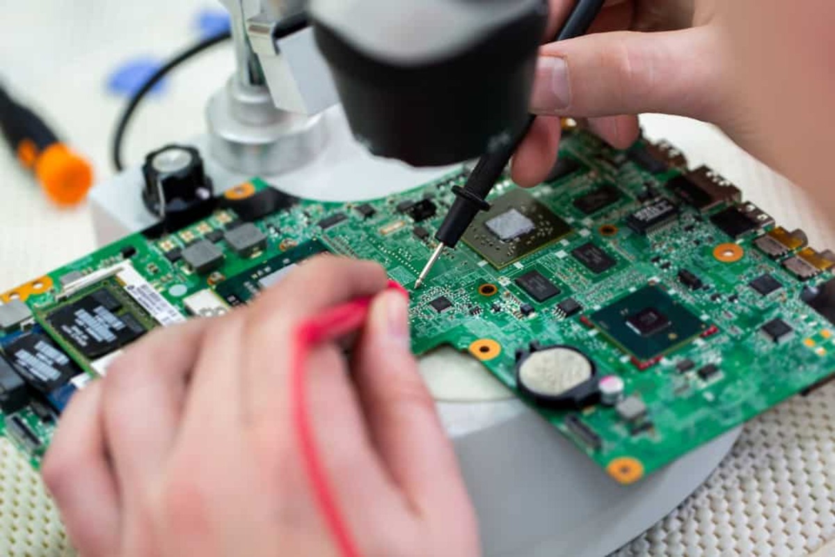
- Multimeter: A multimeter is perhaps the most crucial tool for testing electronic components. It measures voltage, current, and resistance, allowing you to check the health of various components, such as resistors, capacitors, diodes, and transistors.
- Logic Probe: A logic probe is used to test digital circuits. It checks for logic high (1) or logic low (0) signals in a circuit, enabling you to analyze and troubleshoot digital components and circuits.
- Oscilloscope: An oscilloscope is an advanced tool that displays voltage waveforms graphically. It is used to observe and analyze signals in real-time, helping you identify irregularities, glitches, and abnormalities in electronic circuits.
- Signal Generator: A signal generator produces different waveforms, frequencies, and amplitudes. It is used to simulate input signals, allowing you to test the functionality of various electronic components, such as amplifiers, filters, and oscillators.
- Soldering Iron: A soldering iron is used to join or repair electronic components through soldering. It enables you to remove and replace faulty components, ensuring proper connections and continuity.
- Desoldering Pump or Wick: When removing faulty components, a desoldering pump or wick helps in safely extracting solder from the circuit board, enabling easy component replacement.
- Component Tester: A component tester is designed specifically for identifying and evaluating the characteristics of individual electronic components, such as transistors, diodes, capacitors, and resistors.
These are just a few of the basic tools that you should have in your electronics toolkit. They will empower you to efficiently test and diagnose various electronic components, streamlining the troubleshooting process and ensuring a successful repair.
How to Test Resistors
Resistors are one of the most commonly used components in electronic circuits. They limit the flow of electric current and play a crucial role in regulating voltage levels. If you suspect a resistor has failed or need to determine its value, here is a simple step-by-step guide on how to test resistors:
- Preparation: Before testing a resistor, make sure the circuit is powered off and disconnected from the power source to prevent any electrical mishaps.
- Visual Inspection: Examine the resistor for any signs of physical damage, such as discoloration, burns, or cracks. A damaged resistor may indicate a failure.
- Multimeter Setting: Set your digital multimeter to the resistance (ohms) measurement mode. Choose an appropriate range based on the expected resistor value.
- Measure Resistance: Connect the multimeter leads to the resistor. The color bands on the resistor indicate its nominal resistance value. Compare the measured resistance with the expected value.
- Resistance Tolerance: Most resistors have a tolerance value, which indicates the acceptable variation in resistance from the specified value. Ensure that the measured resistance falls within the tolerance range.
- Zero Reading: To ensure accurate readings, short the multimeter leads together and set the meter to zero. This compensates for any resistance in the leads.
- Testing in-Circuit: If the resistor is in a circuit, you can measure its resistance without desoldering it. Ensure that the circuit is powered off, and there are no parallel paths that might affect the reading.
- Replacement: If the measured resistance deviates significantly from the expected value or falls outside the tolerance range, it is likely that the resistor has failed and needs replacement.
Testing resistors is relatively straightforward, thanks to the simplicity of their function. By following these steps and using a multimeter, you can quickly determine the health and value of a resistor, facilitating effective troubleshooting and repair in electronic circuits.
How to Test Capacitors
Capacitors are essential components in electronic circuits, storing and releasing electrical energy. Testing capacitors can help identify faulty or degraded capacitors that may cause circuit malfunctions. Here is a simple guide on how to test capacitors:
- Preparation: Before testing a capacitor, ensure the circuit is powered off and disconnected from the power source to avoid any electrical hazards.
- Visual Inspection: Examine the capacitor for any visible signs of damage, such as bulges, leaks, or a burst top. Any physical anomaly may suggest a faulty capacitor.
- Discharge Capacitor: Discharge the capacitor by shorting its terminals with a resistor or using a discharge tool to remove any residual charge and ensure your safety during testing.
- Multimeter Setting: Set your digital multimeter to the capacitance measurement mode. Choose a range higher than the expected capacitance value.
- Measure Capacitance: Connect the multimeter leads to the capacitor terminals, ensuring the correct polarity. The multimeter will display the measured capacitance value. Compare it to the expected value.
- Polarity: Some capacitors, like electrolytic capacitors, have polarity markings. Ensure you connect the positive and negative terminals correctly during the testing process.
- Leakage Current: In addition to capacitance, some multimeters can measure leakage current. High leakage current readings may indicate capacitor degradation or failure.
- Testing in-Circuit: Capacitors in-circuit can still be tested using a capacitance meter. However, it is vital to disconnect one end of the capacitor from the circuit to avoid parallel paths affecting the measurement.
- Replacement: If the measured capacitance deviates significantly from the expected value or if there are visible signs of damage, it is advisable to replace the capacitor to ensure proper circuit functionality.
By following these steps and using a multimeter with capacitance measurement capability, you can effectively test capacitors and identify any faulty or degraded components. Proper testing will contribute to the overall performance and reliability of your electronic circuits.
How to Test Inductors
Inductors are important components in electronic circuits that store energy in a magnetic field. Testing inductors can help identify any faults or issues that may affect the performance of the circuit. Here is a step-by-step guide on how to test inductors:
- Preparation: Prior to testing an inductor, ensure that the circuit is disconnected from the power source and turned off to prevent any electrical accidents.
- Visual Inspection: Examine the inductor for any physical damage, such as broken wires, loose connections, or signs of overheating. Any noticeable damage may indicate a faulty inductor.
- Multimeter Setting: Set your digital multimeter to the inductance (H/mH/uH) measurement mode. Choose the appropriate range for the expected inductance value of the component.
- Zeroing the Meter: Short the multimeter probes together and press the zero or auto-zero button to eliminate any residual capacitance or resistance in the meter.
- Measure Inductance: Connect the multimeter probes to the terminals of the inductor, ensuring the correct polarity. The multimeter will display the measured inductance value. Compare this value to the expected inductance.
- Testing Inductor Quality: Some multimeters have an option to test the quality factor (Q) of an inductor. This factor indicates how efficiently the inductor stores energy. Higher Q values signify better performance.
- Coil Integrity: In addition to measuring inductance, it is important to check if the coil is intact. Use a magnifying glass to inspect for any broken or disconnected wires within the inductor.
- Testing in-Circuit: Inductors can be tested in-circuit, but it’s important to disconnect one end of the inductor to avoid parallel paths that may affect the measurement.
- Replacement: If the measured inductance significantly deviates from the expected value, or if there are signs of physical damage or coil integrity issues, it is advisable to replace the inductor.
By following these steps and utilizing a suitable multimeter, you can effectively test inductors and ensure their functionality in electronic circuits. Proper testing allows for the identification of faulty components and the maintenance of optimal circuit performance.
How to Test Diodes
Diodes are crucial electronic components that allow current to flow in only one direction. Testing diodes is essential to ensure that they are functioning properly and not causing any issues in the circuit. Here is a step-by-step guide on how to test diodes:
- Preparation: Before testing a diode, make sure the circuit is powered off and disconnected from the power source to prevent any electrical mishaps.
- Visual Inspection: Examine the diode for any physical damage, such as cracks, burns, or loose connections. Any visible damage may indicate a faulty diode.
- Multimeter Setting: Set your digital multimeter to the diode testing mode, usually denoted with a diode symbol. It enables you to measure forward voltage drop and reverse resistance.
- Identify the Diode Polarity: Determine the polarity of the diode. The cathode end is typically marked with a band or a line. Ensure the multimeter leads are connected accordingly.
- Measure Forward Voltage Drop: Connect the positive (red) multimeter lead to the anode and the negative (black) lead to the cathode of the diode. Note the forward voltage drop displayed on the meter, typically around 0.6 to 0.7 volts for silicon diodes.
- Measure Reverse Resistance: Reverse the multimeter leads, connecting the positive lead to the cathode and the negative lead to the anode of the diode. The multimeter should display a high resistance, indicating that the diode is non-conductive in reverse bias.
- Testing in-Circuit: Diodes can be tested in-circuit to some extent. However, it’s important to desolder one end of the diode to avoid parallel paths that might influence the measurement.
- Replacement: If the diode fails the forward voltage drop test or shows low resistance in reverse bias, it is likely defective and should be replaced with a new one.
By following these steps and using a multimeter with a diode testing function, you can effectively test diodes and identify any faulty components that may affect the proper functioning of electronic circuits.
How to Test Transistors
Transistors are crucial components in electronic circuits, amplifying or switching electronic signals. Testing transistors is essential to ensure their functionality and identify any faulty components that may affect circuit performance. Here is a step-by-step guide on how to test transistors:
- Preparation: Before testing a transistor, ensure the circuit is powered off and disconnected from the power source to prevent any electrical accidents.
- Visual Inspection: Examine the transistor for any physical damage, such as broken leads, burns, or visible signs of overheating. Any visible damage may indicate a faulty transistor.
- Transistor Types: Understand the transistor type you are testing. Common types include bipolar junction transistors (BJTs) and field-effect transistors (FETs).
- Multimeter Setting: Set your digital multimeter to the appropriate measuring mode based on the transistor type. For testing BJT transistors, select the diode test mode. For FET transistors, use the resistance mode.
-
Testing BJT Transistors:
- Base-Emitter Junction: Connect the positive lead (red) of the multimeter to the base terminal and the negative lead (black) to the emitter terminal. The multimeter should display a voltage drop between 0.6 and 0.7 volts.
- Base-Collector Junction: Connect the positive lead to the base terminal and the negative lead to the collector terminal. The multimeter should display an open circuit or a high resistance reading.
-
Testing FET Transistors:
- Gate-Source Junction: Connect the positive lead of the multimeter to the gate terminal and the negative lead to the source terminal. The multimeter should display an open circuit or a high resistance reading.
- Drain-Source Junction: Connect the positive lead to the drain terminal and the negative lead to the source terminal. The multimeter should display an open circuit or a high resistance reading.
- Testing in-Circuit: Transistors can be tested in-circuit, but it’s important to desolder one lead from the circuit to avoid parallel paths that might influence the measurement.
- Replacement: If the transistor fails any of the above tests or exhibits irregular behavior, it is likely defective and should be replaced with a new one.
By following these steps and using a multimeter with the appropriate measuring mode, you can effectively test transistors and identify any faulty components that may impact the performance of electronic circuits.
How to Test Integrated Circuits
Integrated circuits (ICs) are complex and compact electronic devices that contain various electronic components and circuits on a single chip. Testing ICs is crucial to ensure their functionality and identify any faulty or damaged components within the chip. Here is a step-by-step guide on how to test integrated circuits:
- Preparation: Before testing an IC, ensure the circuit is powered off and disconnected to prevent any electrical accidents.
- Visual Inspection: Examine the IC for any physical damage, such as bent pins, discoloration, or signs of overheating. Any visible damage may indicate a faulty IC.
- Pin Identification: Study the datasheet of the IC to identify the pin configuration and its corresponding functions.
- IC Tester: Use a specialized IC tester if available. These testers come with socket adapters designed for specific IC packages and can accurately test the functionality of the IC.
- In-Circuit Testing: With the help of a multimeter, you can perform some basic tests on ICs while they are still in the circuit. These tests include measuring the power supply voltages at specific pins and checking for continuity between pins.
- Functional Testing: Functional testing involves applying known input signals to the appropriate pins of the IC and observing the corresponding output signals. This can be done using a signal generator and an oscilloscope or logic analyzer to analyze the response of the IC.
- Replacement: If the IC fails any of the tests, or if its functionality is questionable, it is recommended to replace the IC with a new one to ensure proper circuit performance.
Testing integrated circuits can be challenging due to their complexity. However, by following these steps and utilizing specialized IC testers or performing basic in-circuit and functional testing, you can effectively determine the functionality and integrity of an IC, facilitating accurate troubleshooting and repair of electronic circuits.
How to Test Transformers
Transformers are essential components in electrical and electronic systems, allowing the efficient transfer of electrical energy between circuits. Testing transformers is crucial to ensure their proper functioning and identify any faults or issues that may affect the overall system performance. Here is a step-by-step guide on how to test transformers:
- Preparation: Before testing a transformer, ensure the circuit is powered off and disconnected to prevent any electrical hazards.
- Visual Inspection: Examine the transformer for any visible signs of damage, such as physical cracks, burnt windings, or loose connections. Any physical anomalies may indicate a faulty transformer.
- Resistance Measurement: Use a multimeter to measure the resistance of the primary and secondary windings. Compare the measured resistance values with the manufacturer’s specifications. Higher or lower resistance values could indicate a winding problem.
- Open Circuit Testing: Apply a low voltage AC signal to the primary winding and measure the output voltage on the secondary winding using an oscilloscope or a multimeter. The measured output voltage should match the expected voltage ratio of the transformer.
- Short Circuit Testing: Apply a low voltage AC signal to the secondary winding and measure the input current on the primary winding using a current clamp meter. The measured input current should match the expected ratio based on the transformer’s turn ratio.
- Insulation Testing: To ensure insulation integrity, perform an insulation resistance test using a megohmmeter or insulation resistance tester. Higher insulation resistance values indicate better insulation quality.
- Testing in-Circuit: Transformers can also be tested in-circuit by disconnecting one side of the winding from the circuit and performing the above tests. However, be cautious about other components in the circuit that may influence the test results.
- Replacement: If the transformer fails any of the above tests or exhibits irregular behavior, it is likely defective and should be replaced with a new one to ensure proper operation of the electrical or electronic system.
Testing transformers is important to ensure their performance and reliability. By following these steps and using appropriate testing equipment, you can effectively identify any faults or issues in transformers and take necessary actions to rectify or replace them as needed.
How to Test Relays
Relays are electromagnetic switches that play a crucial role in controlling the flow of electrical currents in various circuits. Testing relays is essential to ensure their proper functionality and to identify any faults or issues that may affect the performance of the circuit they operate in. Here is a step-by-step guide on how to test relays:
- Preparation: Before testing a relay, ensure the circuit is powered off and disconnected to prevent any electrical accidents.
- Visual Inspection: Examine the relay for any physical damage, such as a cracked casing or loose connections. Physical anomalies may indicate a faulty relay.
- Continuity Testing: Using a multimeter set to the continuity test mode, check for continuity between specific relay terminal pairs. Follow the relay datasheet or markings to identify the proper terminals for continuity testing.
- Coil Testing: Measure the resistance across the coil terminals of the relay using a multimeter set to the resistance mode. Compare the measured resistance with the manufacturer’s specifications. A significantly lower or higher resistance reading may indicate a problem with the relay coil.
- Activation Testing: Apply the appropriate voltage across the coil terminals to energize the relay. Listen for an audible click or look for physical movement (if visible) to confirm that the relay is operating correctly.
- Contact Testing: After activating the relay, use a multimeter to measure the resistance or continuity across the relay’s contact terminals. The contacts should open or close (depending on the relay type) as expected when energized.
- Functional Testing: If possible, test the relay in its intended application or circuit to ensure proper functioning under real-world conditions.
- Replacement: If the relay fails any of the above tests or exhibits irregular behavior, it is likely defective and should be replaced with a new one to ensure proper circuit operation.
By following these steps and using appropriate testing equipment, you can effectively test relays for functionality and identify any faults or issues. Proper testing enables you to ensure reliable and safe operation of circuits that utilize relays in various applications.
How to Test Switches
Switches are fundamental components in electronics, allowing the control of current flow within a circuit. Testing switches is crucial to ensure their proper functionality and to identify any faults or issues that may disrupt the circuit operation. Here is a step-by-step guide on how to test switches:
- Preparation: Before testing a switch, ensure the circuit is powered off and disconnected from the power source to prevent any electrical mishaps.
- Visual Inspection: Examine the switch for any physical damage, such as broken parts, loose connections, or signs of wear. Any visible anomalies may indicate a faulty switch.
- Switch Position: Familiarize yourself with the different positions of the switch, such as on/off, open/closed, or momentary, depending on the switch type.
- Continuity Testing: Using a multimeter set to the continuity or resistance mode, measure the continuity between the switch terminals when operated in the desired position. The switch should provide continuity or a low resistance reading in the correct position and an open circuit or high resistance reading in the opposite position.
- Testing Resistance: If the switch has variable resistance (such as a potentiometer or rheostat), measure the resistance across the switch terminals using a multimeter. As the switch is operated, the resistance should vary smoothly and consistently.
- Operational Testing: If possible, test the switch in its intended application or circuit to ensure it functions correctly under real-world conditions.
- Replacement: If the switch fails any of the tests or exhibits irregular behavior, it is likely defective and should be replaced with a new one to ensure proper circuit operation.
By following these steps and using appropriate testing equipment, you can effectively test switches for functionality and identify any faults or issues. Proper testing ensures the reliable and efficient operation of switches in various electronic circuits.
How to Test Fuses
Fuses are essential safety devices in electrical and electronic systems, protecting them from excessive current and preventing potential hazards. Testing fuses is crucial to ensure their proper functioning and to identify any blown or faulty fuses that may compromise circuit protection. Here is a step-by-step guide on how to test fuses:
- Preparation: Before testing a fuse, ensure the circuit is powered off and disconnected to prevent any electrical accidents.
- Visual Inspection: Examine the fuse for any physical damage, such as a broken filament or a discolored casing. Any visible damage indicates a blown or faulty fuse.
- Fuse Type: Understand the type of fuse you are testing, such as a glass tube fuse, blade fuse, or resettable/thermal fuse.
- Continuity Testing: Using a multimeter set to the continuity or resistance mode, place the probes on both ends of the fuse. A functioning fuse should show continuity (a low resistance reading), indicating it is intact and conducting current.
- Visual Fuse Element: For glass tube fuses, a visible break or gap in the internal fuse element indicates a blown fuse. Replace a blown fuse with the same rating and type.
- Resettable/Thermal Fuses: These fuses are self-resetting and can be tested by applying heat to the component until it reaches the specified activation temperature. Once triggered, the fuse should open the circuit and restore it once it cools down.
- Replacement: If a fuse fails the continuity test or shows visible signs of damage, it is likely blown or faulty. Replace it with a new fuse of the same rating and type to maintain circuit protection.
By following these steps and using appropriate testing equipment, you can effectively test fuses and identify any blown or faulty fuses. Proper testing ensures reliable circuit protection and prevents potential damage to electrical and electronic systems.
How to Test Optocouplers
Optocouplers, also known as optoisolators, are electronic components that use light to transfer signals between two isolated circuits. Testing optocouplers is important to ensure their proper operation and to identify any faults or issues that may affect signal transmission. Here is a step-by-step guide on how to test optocouplers:
- Preparation: Before testing an optocoupler, ensure the circuit is powered off and disconnected to prevent any electrical mishaps.
- Visual Inspection: Examine the optocoupler for any physical damage, such as cracks, loose leads, or signs of overheating. Any visible damage may indicate a faulty optocoupler.
- Pin Identification: Study the datasheet or markings on the optocoupler to identify the pin configuration and understand the function of each pin.
- Forward Voltage: Measure the forward voltage drop across the LED side of the optocoupler using a multimeter set to the diode testing mode. The multimeter should indicate a typical forward voltage drop value.
- Resistance Check: Measure the resistance between the different input and output pins of the optocoupler using the resistance mode of a multimeter. A high resistance reading indicates that the optocoupler is not triggered, while a low resistance reading suggests activation.
- Output Voltage: Apply a voltage to the input side of the optocoupler according to the specifications in the datasheet. Measure the voltage output on the output side using a multimeter or an oscilloscope. Ensure that the output voltage matches the expected value.
- Functional Testing: If possible, test the optocoupler in its intended application or circuit to verify signal transmission between the isolated circuits.
- Replacement: If the optocoupler fails any of the above tests or exhibits irregular behavior, it is likely defective and should be replaced with a new one to ensure proper signal isolation and transmission.
By following these steps and using appropriate testing equipment, you can effectively test optocouplers and identify any faults or issues. Proper testing ensures reliable signal transfer and the optimal functioning of optocouplers in electronic circuits.
How to Test LEDs
LEDs (Light Emitting Diodes) are widely used in various electronic devices as a source of light. Testing LEDs is important to ensure their proper functionality and to identify any faulty or damaged LEDs that may affect the illumination or signaling in a circuit. Here is a step-by-step guide on how to test LEDs:
- Preparation: Before testing an LED, ensure the circuit is powered off and disconnected to prevent any electrical accidents.
- Visual Inspection: Examine the LED for any physical damage, such as cracks, discolored components, or loose connections. Any visible damage may indicate a faulty LED.
- Forward Voltage: Identify the forward voltage rating of the LED by referring to its datasheet or product specifications. This information is crucial for selecting the appropriate testing method.
- Multimeter Testing: Set your digital multimeter to the diode testing mode. Connect the positive (red) lead to the anode (longer lead) and the negative (black) lead to the cathode (shorter lead) of the LED. The multimeter should display a forward voltage drop measurement within the specified range.
- Battery Testing: For low-power LEDs, you can use a simple battery and resistor circuit to test their functionality. Connect a suitable resistor in series with the LED and then connect the circuit to a power source. If the LED illuminates, it is functioning correctly.
- Brightness Test: Visually observe the LED to check its brightness level. If the LED is noticeably dim or does not produce any light, it may indicate a faulty LED.
- Multiple LEDs: If testing multiple LEDs, repeat the above steps for each LED individually to ensure accurate results.
- Replacement: If an LED fails any of the tests or exhibits irregular behavior, it is likely defective and should be replaced with a new one to ensure proper lighting or signaling in the circuit.
By following these steps and using appropriate testing equipment, you can effectively test LEDs and identify any faulty or damaged components. Proper testing ensures reliable illumination and signaling in electronic circuits that incorporate LEDs.
How to Test Voltage Regulators
Voltage regulators are essential components in electronic circuits that help maintain a stable output voltage, regardless of changes in input voltage or load conditions. Testing voltage regulators is important to ensure their proper operation and to identify any faults or issues that may result in unstable or incorrect voltage output. Here is a step-by-step guide on how to test voltage regulators:
- Preparation: Before testing a voltage regulator, ensure the circuit is powered off and disconnected to prevent any electrical accidents.
- Visual Inspection: Examine the voltage regulator for any physical damage, such as burnt components, loose connections, or signs of overheating. Any visible anomalies may indicate a faulty regulator.
- Pin Identification: Study the datasheet or markings on the voltage regulator to identify the pin configuration and understand the function of each pin.
- Voltage Output Range: Identify the expected output voltage range for the specific voltage regulator you are testing. This information is crucial for verifying its functionality.
- Voltage Measurement: Use a digital multimeter to measure the output voltage of the regulator. Connect the positive (red) probe to the output pin and the negative (black) probe to the ground pin. Ensure the input voltage is within the specified range.
- Voltage Stability: While measuring the output voltage, observe its stability by monitoring any fluctuations or deviations from the expected value. The voltage should remain steady within the specified tolerance range.
- Overload Testing: Apply a load to the output of the voltage regulator, either by connecting a suitable resistor or a device that draws current. Monitor the output voltage to ensure it remains stable and within the expected range, even under load conditions.
- Thermal Testing: If possible, monitor the temperature of the voltage regulator during operation. Excessive heat may indicate a faulty regulator that is unable to handle the required power dissipation.
- Replacement: If the voltage regulator fails any of the above tests or exhibits irregular behavior, it is likely defective and should be replaced with a new one to ensure a stable and accurate output voltage.
By following these steps and using appropriate testing equipment, you can effectively test voltage regulators and identify any faults or issues. Proper testing ensures reliable and stable voltage regulation in electronic circuits, contributing to the overall performance and functionality of the system.
How to Test Oscillators
Oscillators are electronic circuits that generate periodic waveforms, such as sine waves, square waves, or pulse waves. Testing oscillators is crucial to ensure their proper functioning and to identify any faults or issues that may affect signal generation. Here is a step-by-step guide on how to test oscillators:
- Preparation: Before testing an oscillator, ensure the circuit is powered off and disconnected to prevent any electrical accidents.
- Visual Inspection: Examine the oscillator circuit for any physical damage, such as loose connections, burnt components, or signs of overheating. Any visible anomalies may indicate a faulty oscillator.
- Breadboard or PCB Setup: Set up the oscillator circuit on a breadboard or PCB, ensuring all components are properly installed and connected.
- Power Connection: Connect the power supply to the oscillator circuit, ensuring the correct polarity and voltage.
- Oscilloscope Monitoring: Connect an oscilloscope probe to the output pin or test point of the oscillator circuit. Adjust the oscilloscope settings (such as timebase and voltage scale) to visualize the waveform generated by the oscillator.
- Signal Verification: Observe the waveform displayed on the oscilloscope. Depending on the specific oscillator type, verify if it matches the expected waveform (e.g., sine wave, square wave, etc.) in terms of frequency, amplitude, and shape.
- Frequency Measurement: Use the oscilloscope’s frequency measurement feature to measure the frequency of the generated waveform. Compare this value to the expected frequency specified in the oscillator design or datasheet.
- Frequency Adjustment: If the generated frequency deviates significantly from the expected value, check if there are any adjustable components (such as resistors or capacitors) that can be tuned or calibrated to bring the frequency within the desired range.
- Signal Stability: Observe the waveform displayed on the oscilloscope for any signs of instability, such as fluctuations, drift, or excessive noise, which can indicate a problem with the oscillator circuit.
- Replacement: If the oscillator fails any of the above tests or exhibits irregular behavior, such as the absence of a generated waveform, it is likely defective and should be replaced with a new one to ensure proper signal generation.
By following these steps and using appropriate testing equipment, you can effectively test oscillators and identify any faults or issues. Proper testing ensures accurate and stable waveform generation in electronic circuits that rely on oscillators for timing or signal generation purposes.
How to Test Motors
Testing motors is essential to ensure their proper functioning and identify any faults or issues that may affect their performance. Whether it’s a DC motor, AC motor, or stepper motor, here is a step-by-step guide on how to test motors:
- Preparation: Before testing a motor, ensure the power source is disconnected to prevent any electrical accidents.
- Visual Inspection: Examine the motor for any physical damage, such as loose connections, broken wires, or signs of wear. Any visible damage may indicate a faulty motor.
- Motor Type: Understand the type of motor you are testing and familiarize yourself with its specifications, such as voltage, current, and operating range.
- Power Supply: Connect the motor to an appropriate power supply based on its specifications. Ensure the voltage and current are within the motor’s operating range.
- Motor Rotation: Apply power to the motor and observe its rotation. If it rotates in the desired direction, the motor is functioning correctly. If it rotates in the opposite direction, swap the connections to the power supply.
- Speed Control: If the motor has variable speed control, adjust the input voltage or use a variable voltage source to vary the speed and observe if the motor responds accordingly.
- Load Testing: Attach an appropriate load to the motor, such as a fan blade or a small load wheel, to observe how the motor handles the additional load. It should maintain a stable rotation and not exhibit any significant drops in speed or excessive overheating.
- Amperage Measurement: Use a multimeter or clamp meter to measure the current being drawn by the motor during operation. Compare it to the motor’s rated current to ensure it is within the acceptable range.
- Noise and Vibration: Observe the motor for excessive noise or vibration, which may indicate a problem with the motor’s bearings, alignment, or internal components.
- Replacement: If the motor fails any of the tests or exhibits irregular behavior, such as failure to rotate, excessive overheating, or abnormal noise, it is likely defective and should be replaced with a new one to ensure proper motor functionality.
By following these steps and using appropriate testing equipment, you can effectively test motors and identify any faults or issues. Proper testing ensures the reliable and efficient functioning of motors in various applications, from machinery to robotics to automotive systems.
How to Test Sensors
Testing sensors is crucial to ensure their accuracy, reliability, and proper functionality in various applications. Whether it’s an optical sensor, temperature sensor, proximity sensor, or any other type, here is a step-by-step guide on how to test sensors:
- Preparation: Before testing a sensor, ensure the circuit is powered off and disconnected to prevent any electrical accidents.
- Visual Inspection: Examine the sensor for any physical damage, such as broken wires, bent pins, or signs of wear. Any visible damage may indicate a faulty sensor.
- Datasheet: Study the datasheet or documentation of the sensor to understand its specifications, including operating voltage, signal output, and sensitivity.
- Power Connection: Connect the sensor to a power supply within its operating voltage range. Ensure proper polarity and observe any indicator lights or LED signals present on the sensor.
- Signal Output: Measure the output of the sensor using an appropriate measuring device, such as a multimeter or an oscilloscope. Compare the measured output to the expected range specified in the sensor’s datasheet.
- Functional Testing: Test the sensor under its intended operating conditions. For instance, with a proximity sensor, place an object within its detection range and observe if it triggers the sensor as expected.
- Calibration Check: Some sensors, such as temperature or pressure sensors, may require calibration. Follow the calibration procedure specified in the sensor’s documentation to ensure accurate readings.
- Environmental Factors: Consider any environmental factors that may affect the sensor’s performance. Test the sensor under various conditions, such as temperature, humidity, or ambient light, to ensure its reliability.
- Response Time: Measure the response time of the sensor for detecting changes or stimuli. Compare it to the expected response time to assess the sensor’s efficiency.
- Replacement: If the sensor fails any of the tests or exhibits irregular behavior, such as inconsistent readings or failure to detect stimuli, it is likely defective and should be replaced with a new one to ensure accurate data and reliable performance.
By following these steps and using appropriate testing equipment, you can effectively test sensors and identify any faults or issues. Proper testing of sensors ensures their reliable operation and contributes to the accuracy and effectiveness of various systems and applications.
How to Test Connectors
Testing connectors is important to ensure reliable connections and proper functionality in electronic systems. Connectors play a critical role in facilitating the transmission of signals, power, and data between different components and devices. Here is a step-by-step guide on how to test connectors:
- Preparation: Before testing a connector, ensure the circuit is powered off and disconnected to prevent any electrical accidents.
- Visual Inspection: Examine the connectors for any physical damage, such as bent or broken pins, misaligned contacts, or signs of corrosion. Any visible damage may indicate a faulty connector.
- Cleanliness: Ensure the connectors are clean and free from debris or dirt that may hinder proper connections.
- Continuity Check: Use a multimeter set to the continuity or resistance mode to test if the appropriate pins or contacts in the connector are making a proper electrical connection. Ensure there is continuity between the corresponding pins on both sides of the connector.
- Insertion/Extraction: Test the connector by inserting and extracting it multiple times to verify the ease of use and to ensure secure mechanical engagement.
- Tension Test: Apply gentle pressure to the connector while connected to verify that it remains firmly locked without any unwanted movement or disconnection.
- Signal Integrity: If the connector carries signals, use an oscilloscope or signal generator to check for any signal degradation, attenuation, or noise when passing through the connector.
- Insertion/Withdrawal Force: Measure the force required to insert and withdraw the connector using a suitable force gauge. Compare it to the manufacturer’s specifications to ensure it falls within the acceptable range.
- Environmental Testing: Test the connector under varying environmental conditions, such as temperature, humidity, or exposure to vibration, to ensure it can maintain proper functionality and reliability.
- Replacement: If the connector fails any of the tests or exhibits irregular behavior, such as poor contact, unreliable signal transmission, or difficulty in insertion or withdrawal, it is likely defective and should be replaced with a new connector to ensure proper connections in the system.
By following these steps and using appropriate testing equipment, you can effectively test connectors and identify any faults or issues. Proper testing ensures reliable electrical connections and optimal performance in electronic systems.
How to Test PCBs
Testing printed circuit boards (PCBs) is crucial to ensure their proper functionality and reliability in electronic systems. PCBs contain various electronic components and interconnects that facilitate the proper flow of signals and power. Here is a step-by-step guide on how to test PCBs:
- Preparation: Before testing a PCB, ensure the circuit is powered off and disconnected to prevent any electrical accidents.
- Visual Inspection: Examine the PCB for any physical damage, such as broken traces, burnt components, or signs of overheating. Any visible anomalies may indicate a faulty PCB.
- Inspect Components: Check all components for proper placement, orientation, and soldering. Ensure there are no loose, misplaced, or damaged components.
- Power Connections: Connect the power supply or battery to the PCB, following the correct polarity and voltage specifications.
- Power-On Test: Power on the PCB and observe if the power indicators or LEDs light up to confirm the presence of power.
- Functional Testing: Depending on the specific functionality of the PCB, test each function, such as input/output signals, communication interfaces, or sensor readings. Use appropriate equipment, such as oscilloscopes, logic analyzers, or multimeters, to verify the expected responses.
- Continuity Testing: Use a multimeter set to the continuity or resistance mode to ensure proper connectivity of traces and interconnections on the PCB. Verify that there is continuity between the corresponding points of the circuit.
- Signal Integrity: If the PCB carries high-frequency signals, use an oscilloscope to check for any signal degradation, distortion, or noise along the signal paths.
- Environmental Testing: Test the PCB under various environmental conditions, such as temperature extremes, humidity, or vibration, to ensure its performance remains stable and reliable.
- Replacement: If the PCB fails any of the tests or exhibits irregular behavior, such as non-functional components, faulty connections, or inconsistent responses, it may be a sign of a defective PCB. In such cases, replacing the PCB is often necessary to ensure proper circuit functionality.
By following these steps and using appropriate testing equipment, you can effectively test PCBs and identify any faults or issues. Proper testing ensures the reliability and optimal performance of printed circuit boards in various electronic systems and applications.
Troubleshooting Techniques for Testing Electronic Components
When dealing with faulty electronic components, troubleshooting becomes crucial to identify the root cause of the problem. Here are some effective techniques to help you test and troubleshoot electronic components:
- Visual Inspection: Start by visually inspecting the component and surrounding circuitry for any obvious signs of damage, such as burnt marks, bulging capacitors, or loose connections. This can often give you a clue about the faulty component.
- Testing with Multimeter: Use a digital multimeter to measure voltage, resistance, and continuity across the component. Compare the readings with the expected values specified in the component datasheet or service manual. This can help identify open circuits, short circuits, or components that are out of spec.
- Substitution: If possible, replace the faulty component with a known working one to see if the problem persists. This technique helps to isolate the faulty component and confirms if it is responsible for the issue.
- Functional Testing: Test the component’s functionality by applying the appropriate input signals and observing the output response. For example, in the case of sensors, check if they detect the expected stimuli, or for ICs, verify if they perform their intended functions.
- Signal Tracing: Use an oscilloscope or logic analyzer to trace the signal path and identify any abnormalities or unexpected signals. This technique helps to isolate the point where the signal is being distorted or lost, indicating a faulty component or circuitry.
- Temperature Testing: Apply heat or cold to specific components using a heat gun or freeze spray and observe any changes in behavior. Temperature variations can reveal faulty components that exhibit temperature-dependent issues.
- Reverse Engineering: In complex systems, reverse engineering can be helpful. Analyze the circuit design and compare it to the expected behavior to identify any discrepancies or potential issues that may lead to component failure.
- Collaboration and Reference: Seek advice from experienced technicians, consult service manuals, datasheets, and online forums to get insights into common issues with the specific component or circuit design. This can provide valuable guidance for effective troubleshooting.
- Systematic Approach: Troubleshoot systematically, starting from the power supply, then moving to critical components and circuitry. This approach helps to identify and fix issues in a logical and efficient manner.
- Document and Document: Record your observations, testing procedures, and any changes you make during the troubleshooting process. This documentation can be helpful for future reference and may assist others facing similar issues.
By employing these troubleshooting techniques, you can effectively test and diagnose faults in electronic components and systems. These techniques, coupled with experience and a logical approach, can help you identify and resolve issues efficiently.