
Safety Precautions
Before diving into the process of manually testing a power supply with a multimeter, it is crucial to prioritize your safety. Working with electrical components can be dangerous if proper precautions are not taken. Here are some essential safety measures to follow:
- Ensure that you are working in a well-ventilated area to prevent the buildup of heat and fumes.
- Before starting any work, make sure to turn off the power supply and unplug it from the wall socket. This will minimize the risk of electric shock.
- Always wear appropriate personal protective equipment (PPE) such as safety glasses and gloves to protect yourself from potential harm.
- Verify that the multimeter you are using is in good working condition and has been properly calibrated.
- When handling the power supply, be cautious of any sharp edges or protrusions that may cause injury. Use caution and handle with care.
- Avoid working alone whenever possible. Having a buddy nearby can help in case of an emergency.
- Be mindful of any flammable materials in the vicinity. Keep them away from your working area to prevent potential accidents.
- Do not touch any exposed wires or components with your bare hands. Always use insulated tools to handle electrical connections.
- If you notice any unusual smells, sounds, or signs of damage during the testing process, stop immediately and seek professional assistance.
- Finally, if you are unsure about any step or lack the necessary expertise, it is recommended to consult a qualified technician or electrician.
By following these safety precautions, you can minimize the risks associated with testing a power supply with a multimeter and ensure a safe working environment. Remember, your safety should always be the top priority when working with electrical equipment.
Tools and Equipment Needed
Before starting the manual testing process, ensure that you have the necessary tools and equipment ready. Here is a list of items you will need:
- Multimeter: This is the primary tool needed for testing the power supply. Make sure you have a reliable multimeter that can measure voltage and continuity.
- Screwdriver set: You will need a set of screwdrivers with various sizes and types to disassemble the power supply.
- Anti-static wrist strap: This strap helps to prevent the buildup of static electricity and protects sensitive electronic components from damage.
- Insulated wire cutters: These are essential for cutting and stripping wires without causing any damage.
- Insulated wire strippers: These will help you remove the insulation from the wires without cutting into the conductive material.
- Alligator clips: These clips are useful for securely connecting the multimeter probes to the power supply terminals.
- Electrical tape: You will need electrical tape to insulate any exposed wires or connections during the testing process.
- Optional: Power supply tester: If you have a power supply tester, it can help provide a quick and convenient way to check your power supply’s functionality.
Make sure that all the tools and equipment are in good working condition before you begin. By having these items on hand, you will be well-prepared for testing the power supply manually with a multimeter.
Step 1: Turn off and unplug the power supply
Before beginning the testing process, it is important to ensure that the power supply is completely powered off and disconnected from its power source. This will prevent any potential accidents or electrical shocks while working on the power supply.
To turn off the power supply, locate the power switch on the back panel and flip it into the “Off” position. This will shut down the power supply and cut off the flow of electricity to the components.
After turning off the power supply, unplug it from the wall socket or any other power source it might be connected to. This step is crucial to ensure complete isolation of the power supply from any electrical current.
Once you have turned off and unplugged the power supply, give it some time to discharge any residual electricity stored in capacitors. This will minimize the risk of electrical shocks while handling the power supply.
Remember, safety should always be the top priority when working with electrical equipment. By taking the necessary precautions and disconnecting the power supply from the power source, you are creating a safe working environment for the next steps of the manual testing process.
Step 2: Disassemble the power supply
Now that the power supply is turned off and unplugged, it’s time to begin the process of disassembling it. This will allow you to access the internal components and perform the necessary tests.
Start by locating the screws that secure the casing of the power supply. These screws are usually found on the back panel or the sides of the unit. Use the appropriate screwdriver from your set to carefully remove these screws.
Once the screws are removed, gently slide or lift off the casing of the power supply. Take note of any clips or tabs that may be holding the casing in place and ensure they are properly released before attempting to remove it.
Inside the power supply, you will find a variety of components, such as capacitors, transformers, and circuit boards. Take a moment to familiarize yourself with the layout and arrangement of these components.
If necessary, you can refer to the manufacturer’s documentation or search online for a diagram or guide specific to your power supply model. This will provide you with a better understanding of the internal structure and help you locate the components you need to test.
During the disassembly process, be mindful of any delicate components or wiring connections. Avoid applying excessive force or causing any damage to these parts.
By carefully disassembling the power supply, you will be able to access the components needed for testing in the following steps. Take your time and ensure that you handle the power supply with care to prevent any unnecessary damage.
Step 3: Locate the ATX Connectors
After successfully disassembling the power supply, the next step is to locate the ATX connectors. These connectors are responsible for delivering power to various components of the computer.
The ATX connectors are typically found on the power supply’s circuit board, and they come in different shapes and sizes. The most common types of ATX connectors include the 20-pin or 24-pin main power connector, the 4-pin or 8-pin CPU power connector, and the peripheral connectors for devices such as hard drives and optical drives.
Identifying the ATX connectors can be straightforward if you refer to the power supply’s documentation or search for a diagram specific to your power supply model. These resources will provide clear information on the location and labeling of each connector.
Inspect the circuit board carefully and look for the connectors that match the descriptions in the documentation or diagram. They are usually color-coded or labeled for easy identification.
Take note of the different connectors and their corresponding positions on the circuit board. This will help you later when you are testing the voltage output.
It’s important to handle the connectors with care and avoid applying excessive force when connecting or disconnecting them. This will help prevent any damage to both the connectors and the power supply itself.
Once you have identified and familiarized yourself with the ATX connectors, you are ready to move on to the next step of the manual power supply testing process.
Step 4: Set up the Multimeter
With the power supply disassembled and the ATX connectors identified, it’s time to set up the multimeter for testing. Properly configuring the multimeter will allow you to accurately measure voltage and check for continuity.
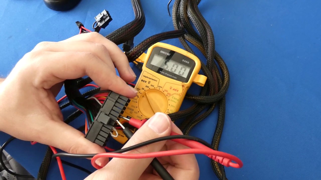
Start by turning on your multimeter and selecting the appropriate settings for voltage measurement. Set the multimeter to the DC (Direct Current) voltage range for accurate readings. Make sure the range is suitable for the voltage levels expected from your power supply, typically 0-30 volts or 0-50 volts.
Next, locate the multimeter’s probes. The red probe is used for positive measurements, and the black probe is used for negative measurements or grounding. Insert the red probe into the positive port (usually labeled “VΩmA+”) and the black probe into the negative port (usually labeled “COM”). Ensure that the probes are securely connected.
Once the multimeter is set up, you may also want to set it to the continuity mode. This mode helps you to check the integrity of the circuit by determining if there is a complete path for the flow of electrical current.
Depending on your multimeter model, you may need to switch the mode dial to the continuity symbol or select the continuity function from the menu. This feature is typically represented by a sound wave symbol or a diode symbol.
Verify that the multimeter is functioning correctly by testing the continuity with the probes connected. When the probes touch, the multimeter should emit a beep or display a low resistance reading, indicating that there is continuity.
By properly configuring the multimeter and testing its functionality, you are ready to move on to the next steps of testing the power supply’s voltage and continuity.
Step 5: Testing the Voltage
Now that the multimeter is properly set up, it’s time to start testing the voltage output of the power supply. This step will help you determine if the power supply is delivering the correct voltage levels to the connected components.
Begin by identifying the ATX connectors that provide power to specific components, such as the main motherboard connector or the CPU connector. Refer to the documentation or diagram specific to your power supply model for accurate identification.
With the power supply turned off and unplugged, carefully connect the multimeter probes to the corresponding pins of the ATX connector. Ensure that the red probe is connected to the positive pin while the black probe is connected to the ground or negative pin.
Once the probes are securely connected, turn on the power supply. This will allow electricity to flow through the circuit and enable you to measure the voltage.
Take note of the expected voltage levels for each pin of the ATX connector based on the power supply’s specifications. Carefully observe the multimeter display and compare the readings you get with the expected values.
A voltage within a reasonable range (typically within ±5%) of the specified value indicates that the power supply is providing the correct voltage to the connected component. However, a significant deviation from the expected values may indicate a potential issue with the power supply.
Repeat the voltage testing for each corresponding pin of the ATX connectors that provide power to critical components such as the motherboard and CPU. This will help identify any discrepancies in voltage output across different connections.
Remember to record the readings and compare them with the manufacturer’s specifications. Any noticeable deviations or fluctuations in voltage should be investigated further or may indicate a need for repair or replacement of the power supply.
By thoroughly testing the voltage output, you can ensure that your power supply is providing the necessary power to your components, potentially avoiding any performance or stability issues in your system.
Step 6: Testing the Continuity
In addition to testing the voltage output, it is important to check the continuity of the power supply’s circuitry. This step will help you identify any breaks or interruptions in the flow of electrical current within the power supply.
Begin by turning off the power supply and disconnecting it from the power source. Make sure that there is no power flowing through the circuitry to avoid any potential risks.
Next, using the continuity mode on your multimeter, carefully touch the probes to different points within the power supply’s circuitry. This can include various solder points, connectors, or any other relevant areas where continuity needs to be ensured.
If there is continuity, meaning there is a complete path for the electrical current, the multimeter will emit a beep or display a low resistance reading. This indicates that the circuit is functioning as it should and there are no breaks or interruptions in the flow of electricity.
On the other hand, if you do not hear a beep or obtain a high resistance reading, it suggests that there is a break or interruption within the circuit. This could be due to a faulty component, loose connection, or damaged wiring that needs to be addressed.
Take note of any points where you detect a lack of continuity and investigate further. This may involve visually inspecting the circuitry, checking for loose connections, or testing individual components to determine the cause of the issue.
It’s worth noting that not all points within the power supply will require continuity, and it is essential to refer to the documentation specific to your power supply model to identify the critical areas to test.
By testing the continuity, you can ensure that the power supply’s circuitry is intact and free from any breaks, providing reliable electrical pathways for proper functionality.
Step 7: Test the Power Supply for any Abnormalities
After testing the voltage output and continuity, it’s important to examine the power supply for any other abnormalities that may indicate a potential issue. This step involves a thorough visual inspection and careful examination of the power supply’s components and overall condition.
Start by visually inspecting the power supply’s circuit board for any signs of physical damage, such as burned or swollen components, charred areas, or leaking capacitors. These can be indications of a faulty power supply that may require repair or replacement.
Check the wiring within the power supply for any loose or disconnected cables. Ensure that all connections are secure and properly plugged in to their respective slots or connectors.
Inspect the fan(s) within the power supply to ensure they are clean and free from dust or obstructions. A buildup of debris can affect the cooling efficiency and overall performance of the power supply.
Check for any unusual noises or vibrations coming from the power supply when it is turned on. These can be indicative of mechanical issues or faulty components within the unit.
Examine the power supply’s exterior for any visible damage such as dents, cracks, or loose parts. Any physical damage to the casing may indicate internal damage as well.
During the testing process, if you encounter any abnormal smells, such as a burning odor, or hear crackling sounds, immediately disconnect the power supply and seek professional assistance. These signs could be indicative of a severe issue that requires expert intervention.
By thoroughly inspecting the power supply for abnormalities, you can identify any potential issues that may affect its functionality, safety, or longevity. Taking note of any observed problems will allow you to take appropriate steps in rectifying the situation, whether that involves repair, replacement, or seeking professional help.
Step 8: Reassembling the Power Supply
Once you have completed the testing and inspection of the power supply, it’s time to reassemble it. Reassembling the power supply correctly is crucial to ensure its proper functioning and to maintain its structural integrity.
Begin by carefully placing the power supply’s casing back onto the unit. Ensure that it aligns properly with the screw holes and securely fasten it with the screws you previously removed. Take care not to overtighten the screws, as this can damage the casing or strip the threads.
Ensure that any clips or tabs that hold the casing in place are properly engaged, providing a snug fit. This will help prevent unnecessary movement or vibrations that could impact the internal components.
Double-check all the connections and wiring within the power supply to ensure they are properly reconnected and secure. Inspect each plug and socket to verify a proper fit, minimizing the risk of loose connections.
Take a moment to clean the exterior of the power supply, especially if any dust or debris has accumulated during the testing and disassembly process. Use a soft cloth or compressed air to remove any unwanted particles, ensuring proper airflow and cooling.
Once the power supply is reassembled and cleaned, plug it back into the appropriate power source and turn it on. Monitor the power supply for any unusual noises, vibrations, or signs of malfunctioning during the startup process.
If the power supply operates normally, without any abnormalities, you can consider the reassembly process successful. However, if you notice any issues or experience any problems, it may be necessary to refer to a professional technician or consider further troubleshooting or repair.
Remember to exercise caution and prioritize safety throughout the reassembly process. This includes ensuring the power supply is completely disconnected from any power sources while reassembling and handling the unit with care to avoid any unnecessary damage.
By following these steps and reassembling the power supply correctly, you can ensure its proper functionality and reliability for future use.