
Checking the Headlight Connector for Physical Damage
Inspecting the headlight connector for physical damage is the first step in diagnosing any headlight issues. A damaged connector can lead to various problems, including intermittent or non-functioning headlights. Follow these steps to ensure the headlight connector is in good condition:
-
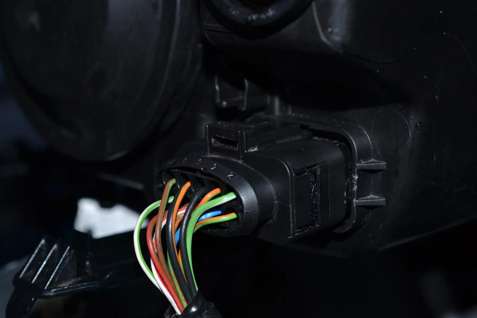
Visual Inspection: Start by visually examining the headlight connector. Look for any signs of physical damage, such as cracks, melted plastic, or exposed wires. These issues can result from overheating, electrical faults, or external damage.
-
Check for Moisture: Moisture ingress can cause corrosion and electrical shorts. Look for any signs of moisture inside the connector or on the terminals. If present, dry the connector thoroughly before proceeding with further tests.
-
Secure Connection: Ensure that the connector is securely attached to the headlight bulb. A loose or improperly connected connector can lead to flickering or intermittent headlight operation.
-
Inspect the Wiring: Examine the wiring leading to the connector for any fraying, cuts, or abrasions. Damaged wiring can impede the flow of electricity to the headlight, resulting in dim or non-operational lights.
-
Verify Proper Fitment: Confirm that the connector fits snugly onto the headlight bulb without any strain on the wires. A loose or ill-fitting connector can lead to electrical arcing and poor connectivity.
-
Look for Discoloration: Check for any discoloration on the connector or wires, as this can indicate overheating or electrical faults. Discolored plastic or wires may signify underlying issues that need to be addressed.
Regularly inspecting the headlight connector for physical damage is crucial for maintaining a reliable lighting system in your vehicle. Identifying and addressing any issues promptly can prevent further damage and ensure optimal headlight performance.
By following these steps, you can effectively assess the physical condition of the headlight connector, paving the way for further testing and troubleshooting to resolve any headlight-related issues.
Testing for Proper Voltage
Ensuring the headlight connector receives the correct voltage is essential for optimal headlight performance. Testing for proper voltage can help identify electrical issues that may affect the brightness or functionality of the headlights. Here’s how to test the voltage:
-
Use a Multimeter: Begin by setting your multimeter to the voltage setting appropriate for your vehicle’s electrical system. Typically, this will be in the range of 12 to 14 volts for a standard automotive battery.
-
Connect the Multimeter: With the vehicle’s headlights turned off, connect the multimeter’s probes to the positive and negative terminals of the headlight connector. Ensure a secure connection to obtain an accurate reading.
-
Check the Voltage: Turn on the vehicle’s headlights and observe the multimeter reading. The voltage should ideally match the manufacturer’s specifications for the vehicle’s electrical system. Deviations from the specified voltage range can indicate an underlying electrical issue.
-
Inspect for Fluctuations: While the headlights are on, monitor the multimeter for any voltage fluctuations. Fluctuations can point to wiring or alternator problems that may affect the consistent delivery of power to the headlights.
-
Compare Across Headlights: If possible, compare the voltage readings between the left and right headlights. Discrepancies in voltage levels may indicate a problem specific to one side, such as a faulty wiring harness or connector.
Testing for proper voltage provides valuable insights into the electrical health of the headlight system. By conducting this test, you can identify and address voltage irregularities that may compromise the effectiveness of the headlights.
Regular voltage testing is an integral part of headlight maintenance, as it allows for early detection of electrical issues that could lead to poor headlight performance. By following these steps, you can ensure that the headlight connector receives the appropriate voltage for optimal functionality.
Inspecting the Wiring and Terminals
Thoroughly inspecting the wiring and terminals associated with the headlight connector is crucial for identifying potential issues that may affect the performance of the headlights. Follow these steps to ensure the wiring and terminals are in optimal condition:
-
Visual Examination: Begin by visually inspecting the wiring leading to the headlight connector. Look for any signs of fraying, cuts, or abrasions on the insulation. Damaged insulation can expose the wires to potential short circuits or moisture ingress.
-
Terminal Condition: Examine the terminals within the headlight connector for signs of corrosion, rust, or damage. Corroded terminals can impede the flow of electricity and lead to poor connectivity, affecting the brightness and functionality of the headlights.
-
Secure Connections: Ensure that all wiring connections leading to the headlight connector are secure and free from any looseness or disconnection. A secure connection is essential for the consistent delivery of power to the headlights.
-
Check for Pinched Wires: Inspect the wiring for any signs of pinching or crimping, especially in areas where the wiring passes through tight spaces or near moving components. Pinched wires can lead to electrical faults and compromised functionality.
-
Verify Insulation Integrity: Confirm that the insulation around the wiring is intact and free from any damage. Proper insulation prevents electrical shorts and ensures the safe and efficient flow of electricity to the headlights.
-
Look for Heat Damage: Check for any signs of heat damage, such as melted insulation or discolored wiring. Heat damage can result from electrical faults or overheating, indicating the need for further inspection and potential repairs.
Inspecting the wiring and terminals associated with the headlight connector is an essential aspect of maintaining a reliable headlight system. By following these steps, you can identify and address any issues that may compromise the electrical integrity and functionality of the headlights.
Regular inspection of the wiring and terminals contributes to the overall safety and performance of the vehicle’s lighting system. By ensuring that the wiring and terminals are in optimal condition, you can mitigate potential electrical issues that could affect the headlights’ effectiveness.
Using a Multimeter to Test the Continuity of the Connector
Employing a multimeter to test the continuity of the headlight connector is a crucial step in diagnosing potential electrical issues that may affect the functionality of the headlights. Follow these steps to effectively test the continuity of the connector:
-
Select the Continuity Setting: Set your multimeter to the continuity or “beep” setting, which allows for the detection of a complete electrical path. This setting enables the multimeter to audibly indicate the presence of continuity across the connector.
-
Probe Placement: With the vehicle’s battery disconnected, place the multimeter probes on the corresponding terminals of the headlight connector. Ensure that the probes make secure contact with the terminals to obtain accurate continuity readings.
-
Check for Audible Signal: While the probes are in place, listen for the audible beep or continuity signal from the multimeter. The presence of the audible signal indicates that there is a complete electrical path across the connector, signifying proper continuity.
-
Verify Across Terminals: Test the continuity across all terminals of the headlight connector to ensure consistent electrical connectivity. Any absence of continuity may indicate a wiring or terminal issue that needs to be addressed.
-
Inspect for Intermittent Continuity: While maintaining contact with the terminals, gently wiggle the wiring leading to the connector. Intermittent beeping or the loss of continuity during movement indicates potential wiring or connector problems that require further investigation.
Utilizing a multimeter to test the continuity of the headlight connector enables the identification of potential wiring or terminal issues that may affect the consistent flow of electricity to the headlights. By following these steps, you can effectively assess the electrical integrity of the connector and address any continuity-related concerns.
Regular continuity testing using a multimeter is essential for maintaining a reliable headlight system. By ensuring that the headlight connector exhibits consistent continuity, you can mitigate potential electrical faults that may compromise the functionality and performance of the headlights.
Checking for Corrosion or Rust
Inspecting the headlight connector for signs of corrosion or rust is vital in maintaining a reliable electrical connection for the headlights. Corrosion and rust can impede the flow of electricity, leading to poor headlight performance. Follow these steps to effectively check for corrosion or rust:
-
Visual Examination: Begin by visually inspecting the terminals and surrounding areas of the headlight connector for any visible signs of corrosion or rust. Look for greenish or bluish deposits, as well as reddish-brown discoloration, which are indicative of corrosion and rust, respectively.
-
Terminal Inspection: Examine the terminals within the headlight connector for any buildup of corrosion or rust. Corroded terminals may appear pitted or discolored, while rust may manifest as reddish deposits. Both can hinder electrical conductivity.
-
Probe Contact Points: With the vehicle’s battery disconnected, gently probe the terminals of the headlight connector to assess the presence of corrosion or rust. Ensure that the probes make sufficient contact to accurately detect any buildup that may affect electrical connectivity.
-
Addressing Corrosion: If corrosion is present, carefully clean the affected terminals using a suitable electrical contact cleaner or a mixture of baking soda and water. Use a small wire brush or abrasive pad to remove the corrosion, restoring proper electrical contact.
-
Preventing Future Corrosion: Apply a thin layer of dielectric grease to the terminals after cleaning to inhibit future corrosion. Dielectric grease acts as a protective barrier, safeguarding the terminals from moisture and oxidation.
Regularly checking for corrosion or rust within the headlight connector is essential for preserving the electrical integrity of the lighting system. By following these steps, you can identify and address any corrosion-related issues that may compromise the functionality of the headlights.
Preventative measures, such as applying dielectric grease after cleaning, can significantly reduce the likelihood of future corrosion, ensuring prolonged electrical reliability within the headlight connector. By addressing corrosion and rust proactively, you can maintain optimal headlight performance and longevity.
Verifying the Ground Connection
Ensuring a secure and functional ground connection for the headlight system is essential for reliable performance. The ground connection completes the electrical circuit, allowing the headlights to operate effectively. Follow these steps to verify the integrity of the ground connection:
-
Locate the Ground Wire: Identify the ground wire associated with the headlight connector. The ground wire is typically connected to the vehicle’s chassis or a dedicated grounding point near the headlight assembly.
-
Visual Inspection: Visually examine the ground wire for any signs of fraying, corrosion, or damage. Ensure that the connection point to the chassis or grounding location is secure and free from rust or debris that may impede electrical conductivity.
-
Perform a Continuity Test: Use a multimeter set to the continuity setting to test the continuity between the ground wire and the vehicle’s chassis or designated grounding point. The multimeter should indicate audible continuity, confirming a solid ground connection.
-
Addressing Grounding Issues: If the continuity test reveals a lack of continuity, inspect the ground wire for breaks or corrosion. Clean the grounding point and the wire terminal to ensure a secure connection, and repair or replace the ground wire if necessary.
-
Consider Ground Strap Replacement: In some cases, vehicles may utilize ground straps to establish electrical connections between components. Inspect these ground straps for signs of wear, corrosion, or damage, and replace them if needed to maintain proper grounding.
Verifying the integrity of the ground connection is crucial for maintaining optimal headlight functionality. By following these steps, you can identify and address any issues related to the ground connection, ensuring consistent electrical flow to the headlights.
Regular inspection and testing of the ground connection contribute to the overall reliability of the headlight system. By confirming a secure ground connection, you can mitigate potential electrical faults and ensure that the headlights operate at their full capacity, providing optimal illumination for safe driving.