
What Is a Crossover Cable?
When it comes to networking, Ethernet cables play a crucial role in connecting devices and facilitating the transfer of data. Among the various types of Ethernet cables available, a crossover cable is a specialized kind that serves a specific purpose. In this article, we’ll dive into what exactly a crossover cable is and when it is necessary to use one.
An Ethernet cable, also known as a network cable or LAN cable, is a physical cable that connects devices together to form a local area network (LAN). It consists of four pairs of wires, each with a unique color code, and is used to transmit data between devices such as computers, routers, switches, and servers.
A crossover cable, on the other hand, is a type of Ethernet cable that allows direct communication between devices of the same type. In a typical Ethernet cable, the pin configuration is designed to send and receive data between different types of devices—for example, connecting a computer to a router. However, when connecting two similar devices, such as two computers, a different wiring arrangement is required, and that’s where a crossover cable comes into play.
The primary distinction between a crossover cable and a regular Ethernet cable, also known as a straight-through cable, lies in the way the wires are connected. In a crossover cable, specific wires are crossed so that the transmitting end of one device is connected to the receiving end of the other device.
Using a crossover cable is necessary when directly connecting two similar devices, such as computer to computer or switch to switch. This is because these devices use the same wiring arrangement for transmission and reception. By using a crossover cable, you can effectively bypass the need for a router or switch, allowing the devices to communicate directly.
If you ever find yourself in need of a crossover cable but don’t have one readily available, fear not! It is possible to create your own crossover cable using a regular Ethernet cable and a pair of wire cutters. By following a simple wiring scheme, you can rearrange the wires in the cable to convert it into a crossover cable. However, it is important to ensure that you have the necessary knowledge and expertise to handle the process correctly.
Understanding Ethernet Cables
Ethernet cables are the backbone of any wired network. They are used to connect devices such as computers, routers, switches, and servers to enable data transmission and communication within a local area network (LAN). To better understand the concept of a crossover cable, it is important to have a basic understanding of Ethernet cables and their different types.
There are several categories of Ethernet cables based on their capabilities and performance. The most commonly used categories are Cat5, Cat5e, Cat6, and Cat6a. These categories differ in terms of their bandwidth capacity, maximum frequency, and level of interference resistance.
Cat5 cables, which are the oldest in the series, are capable of delivering data at speeds of up to 100 Mbps over a maximum distance of 100 meters. Cat5e cables, an improved version of Cat5, support speeds of up to 1,000 Mbps (1 Gbps) and are backward compatible with Cat5. Cat6 cables offer even higher performance with speeds of up to 10 Gbps over shorter distances. Finally, Cat6a cables provide a step further with 10 Gbps speeds over the entire 100-meter range.
When it comes to the physical structure of Ethernet cables, they consist of pairs of wires that are twisted together. These twisted pairs help reduce crosstalk and interference, ensuring better signal quality and faster data transmission. Generally, Ethernet cables use either the unshielded twisted pair (UTP) or the shielded twisted pair (STP) architecture.
The UTP cables are the most common type and come in different categories based on their performance. These cables are lightweight, flexible, and affordable, making them ideal for most networking applications. STP cables, on the other hand, have an added layer of shielding to protect against electromagnetic interference. They are suitable for environments with high levels of electromagnetic interference, such as industrial settings.
It should be noted that both UTP and STP cables can be used to create crossover cables, as the crossover functionality is independent of the cable’s structure. The crossover or straight-through configuration is determined by the wiring arrangement inside the cable.
The Difference Between Straight-Through and Crossover Cables
When it comes to connecting network devices, two types of Ethernet cables are commonly used: straight-through cables and crossover cables. These cables have different wiring arrangements, which determine their functionality and how they are used in a network.
A straight-through cable, also known as a patch cable, is the most commonly used Ethernet cable. It is used to connect devices of different types, such as a computer to a router or a switch to a server. In a straight-through cable, the pin configuration at one end of the cable is exactly the same as the pin configuration at the other end. This means that the transmitting pins at one end are connected to the receiving pins at the other end.
On the other hand, a crossover cable is specifically designed to connect devices of the same type directly. In a crossover cable, certain wires are crossed or swapped to create a direct link between the transmitting pins of one device and the receiving pins of the other device. This allows for direct communication between the devices without the need for an intermediary device like a router or switch.
The main difference between straight-through and crossover cables lies in the wiring arrangement of the cables. In a straight-through cable, the wiring follows the T568B standard, where pin 1 on one end is connected to pin 1 on the other end, pin 2 to pin 2, and so on. This configuration ensures proper communication between devices of different types.
On the other hand, a crossover cable follows a different wiring arrangement known as the T568A standard. In this configuration, the transmitting pins of one device are connected to the receiving pins of the other device. Pin 1 on one end is connected to pin 3 on the other end, pin 2 to pin 6, pin 3 to pin 1, and so on. This crossed wiring allows for direct device-to-device communication.
It’s important to note that not all devices require the use of a crossover cable for direct connection. Many modern devices, such as computers and switches, have auto-MDI/MDIX technology, which automatically detects the cable type and adjusts the pin configuration as needed. This means that even if you use a straight-through cable to connect two devices, they can still establish a connection without any issues.
However, there are scenarios where using a crossover cable is necessary. For example, if you’re connecting two older devices that don’t support auto-MDI/MDIX, or if you’re creating a direct connection between two devices without the presence of a router or switch, a crossover cable is required.
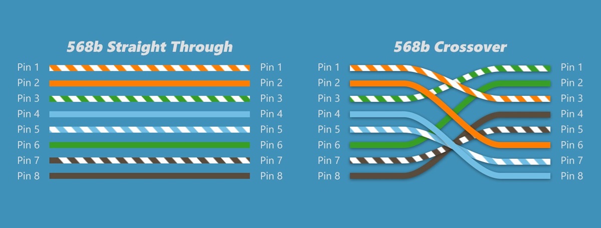
Pin Configuration of Straight-Through Cables
Straight-through cables are the most common type of Ethernet cables used to connect devices of different types in a network. The pin configuration of a straight-through cable follows the T568B standard, which ensures proper communication between devices. Understanding the pin configuration is essential when creating or troubleshooting network connections.
The T568B standard specifies the arrangement of the eight pins in an Ethernet cable, with each pin serving a specific purpose. The pinout starts from the left side of the RJ45 connector, looking at the contacts facing towards you.
- Pin 1 (white/orange) – Transmit + (TD+)
- Pin 2 (orange) – Transmit – (TD-)
- Pin 3 (white/green) – Receive + (RD+)
- Pin 4 (blue) – Not used (Reserved for future use)
- Pin 5 (white/blue) – Not used (Reserved for future use)
- Pin 6 (green) – Receive – (RD-)
- Pin 7 (white/brown) – Not used (Reserved for future use)
- Pin 8 (brown) – Not used (Reserved for future use)
As per the T568B standard, a straight-through cable connects the transmitting pins (TD+) of one device to the receiving pins (RD+) of the other device. Similarly, the transmitting pins (TD-) of one device are connected to the receiving pins (RD-) of the other device. Pins 4, 5, 7, and 8 are not used and are reserved for future use.
This pin configuration allows for proper data transmission between different types of devices. For example, when connecting a computer to a router or a switch, the transmitting pins of the computer’s Ethernet port must be connected to the receiving pins of the router or switch’s Ethernet port, and vice versa.
It is worth noting that if you are using a straight-through cable to connect devices that support auto-MDI/MDIX technology, the pin configuration becomes less critical. Auto-MDI/MDIX technology allows the devices to automatically detect the cable type and adjust the pin configuration as needed. This means that even if the cable is not wired according to the T568B standard, the devices can still establish a connection.
However, it is recommended to follow the T568B standard when creating Ethernet cables, as it is widely accepted and ensures compatibility with various devices. Maintaining consistency in the pin configuration across your network will help prevent confusion during installation, troubleshooting, and future expansions or upgrades.
Pin Configuration of Crossover Cables
Crossover cables are a specialized type of Ethernet cable used to connect devices of the same type directly. Unlike straight-through cables, which are used to connect devices of different types, crossover cables have a different pin configuration that allows for direct communication between devices without the need for an intermediary device. Understanding the pin configuration of crossover cables is essential for proper networking.
The pin configuration of a crossover cable follows the T568A standard, which is different from the T568B standard used for straight-through cables. The T568A standard specifies the arrangement of the eight pins in an Ethernet cable, with each pin serving a specific purpose. The pinout starts from the left side of the RJ45 connector, looking at the contacts facing towards you.
- Pin 1 (white/green) – Transmit + (TD+)
- Pin 2 (green) – Transmit – (TD-)
- Pin 3 (white/orange) – Receive + (RD+)
- Pin 4 (blue) – Not used (Reserved for future use)
- Pin 5 (white/blue) – Not used (Reserved for future use)
- Pin 6 (orange) – Receive – (RD-)
- Pin 7 (white/brown) – Not used (Reserved for future use)
- Pin 8 (brown) – Not used (Reserved for future use)
In a crossover cable, unlike a straight-through cable, specific pins are crossed or swapped. This means that the transmitting pins (TD+) of one device are connected to the receiving pins (RD+) of the other device, and the transmitting pins (TD-) of one device are connected to the receiving pins (RD-) of the other device. The crossed wiring allows for direct device-to-device communication without the need for an intermediary device like a router or switch.
Similar to straight-through cables, pins 4, 5, 7, and 8 in a crossover cable are not used and are reserved for future use. While it is possible to create a crossover cable by manually cross-wiring a straight-through cable, it is more convenient to use an off-the-shelf crossover cable.
It’s important to note that while crossover cables were commonly used in the past to connect devices directly, many modern devices now have auto-MDI/MDIX technology. This technology automatically detects the cable type and adjusts the pin configuration as needed, allowing for direct connection with a straight-through cable. However, it’s still useful to have crossover cables on hand for older devices or situations where auto-MDI/MDIX is not supported.
When using a crossover cable in a network setup, it is crucial to ensure that both devices at either end of the cable are configured in the same way. The pin configuration on one end of the cable should match the pin configuration on the other end to establish a successful connection.
When to Use a Crossover Cable
A crossover cable is specifically designed to connect devices of the same type directly, without the need for an intermediary device like a router or switch. While the use of crossover cables has diminished in recent years due to the widespread adoption of auto-MDI/MDIX technology, there are still scenarios where a crossover cable is necessary.
The primary use case for a crossover cable is when you need to establish a direct connection between two similar devices. This includes connecting two computers, two switches, or two routers. In these situations, using a crossover cable enables direct device-to-device communication.
In older networking setups, using a crossover cable was common when connecting computers for file sharing or playing multiplayer games without the need for an external network switch or hub. However, with the advancement of technology, many modern devices now support auto-MDI/MDIX, which automatically detects and adjusts the pin configuration of the cable to establish a connection, regardless of whether it is a straight-through or crossover cable. This feature has made crossover cables less prevalent in typical home or office network setups.
However, there are still scenarios where using a crossover cable is necessary. One example is when connecting two older devices that don’t support auto-MDI/MDIX technology. In such cases, using a crossover cable is the only way to establish a direct connection between the devices.
Another situation where a crossover cable may be needed is when you want to create a temporary network without a router or switch. For instance, if you need to transfer files or share resources directly between two computers, a crossover cable can facilitate this direct connection.
It’s important to mention that most modern networking devices, such as computers, switches, and routers, now come with auto-MDI/MDIX support. This means that even if you mistakenly use a straight-through cable instead of a crossover cable, the devices will automatically detect the cable type and adjust the pin configuration accordingly to establish a connection. However, using the correct cable type, such as a crossover cable, ensures the most reliable and compatible connection in scenarios where auto-MDI/MDIX is not available or disabled.
Overall, while the need for crossover cables has diminished in recent years, they still serve a purpose in specific networking scenarios, particularly when connecting older devices or establishing a direct connection without the presence of a router or switch.
Making Your Own Crossover Cable
If you find yourself in a situation where you need a crossover cable but don’t have one readily available, fear not! It is possible to create your own crossover cable using a regular Ethernet cable and a pair of wire cutters. Although it may seem daunting, making a crossover cable is a fairly simple process.
Before you begin, gather the necessary tools: a length of Ethernet cable, wire cutters, and a reference guide for the pin configuration. The most commonly used pin configuration for crossover cables follows the T568A standard.
Here’s a simple step-by-step guide to making your own crossover cable:
- Strip approximately 2 inches (5 centimeters) of the outer jacket from both ends of the Ethernet cable using the wire cutters.
- Carefully untwist the pairs of wires and arrange them according to the T568A standard. The pinout should be as follows:
- Pin 1 (white/green) – Transmit + (TD+)
- Pin 2 (green) – Transmit – (TD-)
- Pin 3 (white/orange) – Receive + (RD+)
- Pin 4 (blue) – Not used (Reserved for future use)
- Pin 5 (white/blue) – Not used (Reserved for future use)
- Pin 6 (orange) – Receive – (RD-)
- Pin 7 (white/brown) – Not used (Reserved for future use)
- Pin 8 (brown) – Not used (Reserved for future use)
- On one end of the cable, crimp the wires into an RJ45 connector according to the T568A pin configuration.
- On the other end of the cable, crimp the wires into an RJ45 connector, but this time arrange them in the following order:
- Pin 1 (white/orange) – Receive + (RD+)
- Pin 2 (orange) – Receive – (RD-)
- Pin 3 (white/green) – Transmit + (TD+)
- Pin 4 (blue) – Not used (Reserved for future use)
- Pin 5 (white/blue) – Not used (Reserved for future use)
- Pin 6 (green) – Transmit – (TD-)
- Pin 7 (white/brown) – Not used (Reserved for future use)
- Pin 8 (brown) – Not used (Reserved for future use)
- Once the connectors are crimped, ensure that all the wires are securely attached and that the pin configuration is correct.
- Finally, test the newly made crossover cable by connecting the devices you wish to communicate with. If the devices establish a connection and can communicate successfully, your homemade crossover cable is ready to be used.
Remember, creating your own crossover cable requires careful attention to detail and precision. If you’re uncertain about the process or lack the necessary tools, it’s best to purchase a pre-made crossover cable from a reputable supplier.
Having a properly functioning crossover cable on hand can be incredibly useful, especially in situations where direct device-to-device communication is necessary.
Testing Your Crossover Cable
After making your own crossover cable or purchasing one, it is essential to test its functionality before using it in your network setup. Testing will ensure that the cable is correctly wired and capable of facilitating direct communication between devices. Fortunately, testing a crossover cable is a reasonably straightforward process.
Here’s a step-by-step guide on how to test your crossover cable:
- Connect one end of the crossover cable to the transmitting device, such as a computer.
- Connect the other end of the crossover cable to the receiving device, such as another computer or a switch.
- Power on both devices and wait for them to establish a network connection.
- On the transmitting device, open a command prompt or terminal window.
- Type the command “ipconfig” (Windows) or “ifconfig” (MacOS/Linux) to display the network configuration.
- Look for the IP address assigned to the transmitting device’s Ethernet interface. It should have a valid IP address, subnet mask, and default gateway.
- On the receiving device, perform the same command to check its network configuration.
- If the receiving device also has a valid IP address, subnet mask, and default gateway, it indicates that the crossover cable is functioning correctly and the devices are communicating.
It’s important to ensure that both devices have IP addresses in the same subnet. For example, if the transmitting device has an IP address of 192.168.1.2 with a subnet mask of 255.255.255.0, the receiving device should have an IP address within the same range, such as 192.168.1.3 with the same subnet mask.
If the devices fail to establish a network connection or have incorrect network configurations, there may be an issue with the crossover cable. In such cases, you should double-check the cable’s wiring, making sure that the pin configuration is correct on both ends of the cable. Verify that the corresponding pins are correctly connected between the transmitting and receiving devices.
Aside from checking network connectivity, you can also test the crossover cable by transferring files between the devices or performing other network activities. If the devices can communicate and exchange data successfully, it confirms that the crossover cable is working as intended.
Testing your crossover cable helps avoid issues such as miscommunication or connection problems when using the cable in your network setup. By ensuring its proper functioning beforehand, you can have confidence in the reliability of your direct device-to-device communication.
Ethernet Cables for Different Networking Devices
When it comes to networking devices, such as computers, routers, switches, and servers, selecting the appropriate Ethernet cable is crucial for establishing reliable and efficient connections. Different devices have varying requirements, and choosing the right type of cable ensures optimal performance. Here are some considerations for selecting Ethernet cables for different networking devices:
Computers: For desktop computers, laptops, or any other devices with Ethernet ports, using a standard Category 5e (Cat5e) or Category 6 (Cat6) Ethernet cable is commonly sufficient. These cables support gigabit Ethernet speeds (up to 1 Gbps) and provide reliable data transmission for most home or office setups.
Routers: Routers, as devices responsible for connecting multiple devices to a network, typically have multiple Ethernet ports. For the connections between routers and modems or between routers and switches, Cat5e or Cat6 cables are suitable. These cables can handle high-speed data transmission within the local network and ensure reliable internet connectivity.
Switches: Switches facilitate network connections between multiple devices within a local network. They often have numerous Ethernet ports where devices can be connected. To achieve optimal performance, using Cat6 or Cat6a cables for interconnections between switches or connecting switches to other devices is recommended. These cables can support higher bandwidths and faster data transmission speeds, resulting in efficient network operations.
Servers: Servers are essential for storing and delivering data within a network. They usually require higher data transfer rates and greater reliability. For connecting servers to switches or other networking components, Cat6 or Cat6a cables are ideal. These cables provide the necessary bandwidth for high-speed data transmission, ensuring efficient server performance and reducing network latency.
It’s important to consider the distance between devices when selecting Ethernet cables. The maximum cable length for Ethernet is 100 meters (328 feet). If devices are located farther apart, fiber optic cables or Ethernet extenders can be used to bridge the distance without sacrificing performance. However, for most standard home or office setups, the maximum length of 100 meters is typically sufficient.
Additionally, it’s worth noting that Ethernet cables can be used interchangeably between different networking devices. Auto-MDI/MDIX technology, which is now commonly supported by most devices, allows for automatic detection and adjustment of the cable type. This means that straight-through and crossover cables can both be used effectively, offering more flexibility in network configuration.
Overall, selecting the right Ethernet cable for each networking device ensures optimal performance, data integrity, and reliable connectivity within your network. Understanding the requirements of your devices and considering factors such as speed, distance, and compatibility will help you make informed decisions when choosing Ethernet cables.
Buying Crossover Cables Online
If you’re in need of a crossover cable for your networking setup, buying one online is a convenient and efficient option. Online shopping provides a wide range of choices, competitive pricing, and the convenience of doorstep delivery. Here are some considerations to keep in mind when purchasing crossover cables online:
Reliable Online Retailers: Start by choosing reputable online retailers that specialize in networking equipment. Well-known websites such as Amazon, Newegg, and Best Buy offer a vast selection of crossover cables from various brands and sellers. These platforms also provide customer reviews and ratings, giving you valuable insights into the quality and performance of the cables.
Cable Length: Determine the required length of the crossover cable based on the distance between the devices you want to connect. Ensure that the cable length you choose is appropriate for your networking setup. It’s generally a good idea to add a bit of extra length to accommodate any unforeseen cable routing or positioning requirements.
Cable Category: Consider the category of the crossover cable you need. Most modern setups will benefit from Cat5e, Cat6, or Cat6a cables. However, if you have specific requirements or a particular standard to adhere to, ensure that the cable you select meets those specifications.
Quality and Certification: Look for crossover cables that are made with high-quality materials. Check if they are certified by reputable organizations such as the Telecommunications Industry Association (TIA) or the International Electrotechnical Commission (IEC). Certification provides assurance that the cables meet industry standards and undergo rigorous testing for performance and reliability.
Brand Reputation: Consider the reputation and reliability of the brand when making your purchase. Established brands often have better quality control processes and provide better customer support in case you encounter any issues with the product.
Price and Warranty: Compare prices from different sellers for similar crossover cables to ensure you’re getting the best value for your money. Additionally, check if the cable comes with a warranty or guarantee. A warranty provides peace of mind and protection in case of any manufacturing defects or early failures.
Customer Reviews and Ratings: Take the time to read customer reviews and ratings of the crossover cable you intend to purchase. Pay attention to feedback regarding performance, durability, and compatibility with various devices. These insights can help you make a more informed decision and avoid potential pitfalls.
By following these considerations and guidelines, you can confidently purchase a suitable and reliable crossover cable online. Reading product descriptions, checking compatibility, and understanding your networking requirements will ensure that you make a well-informed decision when selecting the right crossover cable for your specific needs.