
What is a breadboard?
A breadboard is an essential tool in electronics prototyping. It is a reusable solderless device used to build and test electronic circuits quickly and easily. Often referred to as a prototyping board or a plugboard, it allows users to connect and disconnect components without the need for soldering or making permanent connections.
At its core, a breadboard consists of a flat board with numerous interconnected holes and conductive metal strips underneath the board’s surface. These interconnected holes are arranged in a grid pattern, typically with rows and columns or a combination of both. The holes act as electrical junctions, allowing components such as resistors, capacitors, and integrated circuits (ICs) to be inserted and connected together using jumper wires.
One of the breadboard’s key features is its ability to accommodate both through-hole components and surface mount components. Through-hole components, which have leads or pins that can fit into the breadboard’s holes, are easily inserted and connected. On the other hand, surface mount components can be mounted on breakout boards or adapter modules specifically designed to fit the breadboard’s hole spacing.
Most breadboards also feature power rails, which are long columns on the sides of the board used for power and ground connections. These power rails allow for easy distribution of voltage and ground connections to multiple components within the circuit.
Breadboards are often used by electronics hobbyists, students, and professionals to quickly prototype and test circuits before making them into permanent designs. They provide a convenient and flexible platform for experimenting with different circuit configurations and component arrangements.
Overall, breadboards are an invaluable tool in the world of electronics. They allow for rapid circuit prototyping and testing, making them an essential part of any electronics enthusiast’s toolkit.
Components of a breadboard
A breadboard is comprised of several key components that work together to facilitate circuit prototyping and testing. Understanding these components is essential for effectively utilizing the breadboard for your electronics projects.
1. Holes: The breadboard consists of numerous interconnected holes arranged in a grid pattern. These holes are used to insert and connect components, such as resistors, capacitors, and ICs, to build a circuit. The holes are typically grouped in rows and columns, with each row having multiple interconnected holes that facilitate electrical connections.
2. Power Rails: Power rails are long columns located on the sides of the breadboard. These columns are used for power and ground connections. The power rail on one side is for connecting positive (VCC or +) voltage, while the other side is for connecting negative (GND or -) voltage. These power rails serve as convenient distribution points for providing power and ground connections to multiple components in a circuit.
3. Jumper Wires: Jumper wires are essential for establishing connections between components on the breadboard. These wires act as bridges, allowing electricity to flow between different holes and components. Jumper wires come in different lengths, colors, and types (e.g., male-to-male, male-to-female, female-to-female) to accommodate various circuit configurations.
4. Buses: Buses are sets of interconnected holes that run horizontally or vertically across the breadboard. They provide a convenient way to establish common connections between multiple components. Buses are often used for connecting power and ground lines to multiple components simultaneously.
5. Binding Posts: Some breadboards feature binding posts or screw terminals that allow for secure connections to external power sources or other devices. These posts provide a more stable and durable connection for projects that require higher voltages or currents.
6. Notches and Indicators: Breadboards may have notches or indicators to mark specific sections or reference points on the board. These notches can be helpful for aligning components or positioning them in the correct orientation.
Understanding the components of a breadboard is essential for effectively using one in your circuit prototyping. By utilizing the holes, power rails, jumper wires, buses, binding posts, and other features, you can easily connect, test, and modify electronic circuits without the need for soldering or permanent connections.
How does a breadboard work?
A breadboard is a versatile tool that simplifies the process of prototyping and testing electrical circuits. It works by providing a platform for connecting various electronic components together without the need for soldering or permanent connections. Understanding how a breadboard works is crucial for effectively utilizing its capabilities.
1. Holes and Conductive Strips: The breadboard consists of interconnected holes and conductive metal strips underneath its surface. The holes allow you to insert electronic components, while the conductive strips provide electrical connections between these components. These strips are typically arranged in rows and columns, where each row has its own conductive strip. When a component is inserted into a hole, it bridges the gap between two rows, establishing an electrical connection.
2. Power Rails: A breadboard typically features power rails on its sides. These power rails act as convenient distribution points for connecting power and ground to multiple components in a circuit. The power rail on one side is typically used for positive voltage (VCC or +), while the other side is used for negative voltage or ground (GND or -).
3. Jumper Wires: Jumper wires are used to create connections between different holes and components on the breadboard. These wires can be inserted into the holes and connected to the desired components to establish electrical pathways. Jumper wires come in different lengths, colors, and types, making it easy to route connections across the breadboard.
4. Component Placement: When using a breadboard, it’s important to understand the layout and arrangement of the conductive strips. Typically, the strips in each row are interconnected, while the strips in different rows are isolated. This means that components placed on the same row will be connected, while components placed on different rows will not interact unless connected by jumper wires.
5. Prototyping and Testing: Breadboards facilitate the rapid prototyping and testing of electronic circuits. You can easily insert and remove components, rearrange connections, and experiment with different circuit configurations. This allows you to test the functionality of a circuit without the need for permanent connections, making it easy to troubleshoot and modify designs.
Overall, a breadboard provides a convenient platform for building and testing circuits. By understanding how the holes, conductive strips, power rails, jumper wires, and component placement work together, you can effectively utilize a breadboard for prototyping and testing your electronic projects.
Types of breadboards
Breadboards come in various types to suit different needs and project requirements. Each type has its own design and features, offering flexibility and adaptability for different electronic prototyping scenarios. Understanding the different types of breadboards can help you choose the right one for your projects.
1. Full-size Breadboards: Full-size breadboards are the most common and widely used type. They typically have a standard size of 830 or 840 connection points, offering ample space for prototyping larger circuits. Full-size breadboards often feature multiple power rails and multiple buses, allowing for more complex circuit configurations.
2. Mini Breadboards: Mini breadboards are smaller in size compared to full-size breadboards, making them more portable and space-efficient. They usually have around 300 to 400 connection points, making them suitable for smaller and simpler circuit designs. Mini breadboards are often used for quick prototyping or for projects with limited space constraints.
3. Solderless Breadboards: Solderless breadboards are designed for hassle-free circuit prototyping without the need for soldering. They have interconnected holes and conductive strips, allowing components to be easily inserted and connected together using jumper wires. Solderless breadboards offer reusability and flexibility, making them ideal for rapid iterations and experimentation.
4. Modular Breadboards: Modular breadboards consist of several smaller breadboards that can be combined or separated as needed. They feature interlocking mechanisms that allow multiple modules to be interconnected, creating a larger prototyping area. Modular breadboards are convenient for expanding the prototyping space or creating separate sections for different circuit components.
5. Wire Wrapping Breadboards: Wire wrapping breadboards are specifically designed for wire wrapping techniques. They have smaller and closer-spaced holes, allowing wires to be tightly wrapped around the posts to create secure connections. Wire wrapping breadboards are commonly used in more precise and permanent circuit designs where soldering is not desired.
6. Surface Mount Breadboards: Surface mount breadboards are designed to accommodate surface mount components (SMD) that don’t have leads fitting into standard breadboard holes. They feature breakout boards or adapter modules with specific hole spacing to accommodate the smaller size and arrangement of SMD components.
Each type of breadboard offers its own advantages and suitability for different projects. Consider the size, number of connection points, reusability, and specific requirements of your project when choosing the right type of breadboard.
Advantages of using a breadboard
Using a breadboard for electronics prototyping offers several advantages that make it a preferred choice for beginners, hobbyists, and professionals alike. Understanding the advantages of using a breadboard can help you harness its full potential in your circuit design and testing processes.
1. No soldering required: One of the key advantages of using a breadboard is the absence of soldering. This allows for hassle-free experimentation and modification of circuits. Components can be easily inserted and removed from the breadboard, enabling rapid prototyping without the need for permanent connections.
2. Reusable: Breadboards are reusable, making them a cost-effective solution for multiple projects. Unlike printed circuit boards (PCBs), which require intricate design and manufacturing processes, breadboards allow for easy reconfiguration and reuse of components. This flexibility promotes quick iteration and experimentation in the design process.
3. Rapid circuit prototyping: Breadboards facilitate rapid circuit prototyping, significantly reducing the time required to test ideas and concepts. The interconnected holes and conductive strips on the breadboard enable quick and easy connections between various electronic components, allowing you to see the results of your circuit design in real-time.
4. Easy troubleshooting: Due to the plug-and-play nature of breadboards, troubleshooting becomes much simpler. If a component or connection is not functioning as intended, it can be easily identified and replaced or modified without any damage to the breadboard or components. This allows for efficient identification and resolution of circuit issues.
5. Flexibility in circuit design: Breadboards offer flexibility in circuit design and modification. Components can be easily repositioned or rearranged to optimize circuit functionality or accommodate additional components. This flexibility encourages experimentation and the exploration of different circuit configurations and designs.
6. Education and learning: Breadboards are widely used in educational settings to teach electronics and circuit design concepts. They provide hands-on experience and a tangible platform for students to understand the principles of electronics and experiment with circuits. Breadboards promote interactive learning and enhance the understanding of electrical components and their interconnections.
Overall, the advantages of using a breadboard, including its solderless nature, reusability, rapid prototyping capabilities, ease of troubleshooting, flexibility in circuit design, and educational value, make it a valuable tool for electronics enthusiasts and professionals.
Disadvantages of using a breadboard
While breadboards offer many advantages, they also have some limitations and drawbacks that should be considered. Understanding the disadvantages of using a breadboard can help you make informed decisions and overcome potential challenges in your electronics projects.
1. Limited durability: Breadboards are not designed for long-term or high-stress applications. Constant insertion and removal of components, as well as the use of jumper wires, can cause wear and tear over time. The contacts within the breadboard may become loose or develop poor connectivity, impacting the reliability of the circuit.
2. Restricted current and voltage: Breadboards have certain limitations when it comes to the amount of current and voltage they can handle. The conductive strips and connections on the breadboard are not optimized for high currents or high voltages. Exceeding these limits can result in poor circuit performance or damage to the components or breadboard itself.
3. Space constraints: Depending on the size of the breadboard, there may be limited space available for larger or more complex circuits. Full-sized breadboards offer more space, but mini breadboards or modular breadboards may have restrictions on the number of components that can be accommodated. This can be a challenge when working on projects that require a higher number of components.
4. Unreliable connections: While breadboards generally provide reliable connections, they can sometimes result in intermittent connections or signal loss. This is especially true when using jumper wires or when the breadboard contacts become worn out. It’s important to double-check and secure connections to avoid signal interruptions or false readings in your circuit.
5. Limited compatibility with surface mount components: Despite the availability of surface mount breadboards, traditional breadboards are not well-suited for surface mount components (SMDs). These components, which have smaller sizes and different lead arrangements, may not fit into standard breadboard holes. Adapters and breakout boards are often needed to use SMDs effectively with a breadboard.
6. Interference and noise: Breadboards can introduce additional noise and interference into the circuit due to the loose connections and imperfect conductivity of the contacts. This can be problematic, particularly in sensitive circuits or when working with high-frequency signals. Proper grounding and shielding techniques should be considered to minimize noise and ensure accurate circuit measurements.
Despite these disadvantages, breadboards remain a valuable tool for rapid prototyping and learning purposes. Being aware of the limitations can help you plan and mitigate potential issues while effectively utilizing the advantages of breadboards in your electronics projects.
Tips for using a breadboard effectively
When using a breadboard for your electronics projects, it’s important to follow best practices to ensure smooth prototyping and reliable circuit connections. These tips can help you make the most out of your breadboard experience and optimize your circuit designs.
1. Plan your circuit: Before starting, plan your circuit design on a piece of paper or use a circuit diagram tool. This will help you visualize the components, their connections, and the layout on the breadboard, minimizing errors and confusion during the assembly process.
2. Organize your components: Keep your components organized and easily accessible. Use component storage boxes or small containers to prevent mix-ups and loss of small pieces. Proper organization will save you time and frustration when searching for specific components.
3. Start with a clean breadboard: Ensure that your breadboard is clean and free from debris or previous solder residue. Use a brush or compressed air to remove any particles that could interfere with the connections or cause short circuits.
4. Use proper jumper wires: Select the appropriate jumper wires for your circuit connections. Use different colors to keep track of different signal paths. Choose jumper wires with suitable lengths to avoid excessive wire bending or clutter on the breadboard.
5. Avoid excessive wire lengths: Use the shortest jumper wire lengths possible to minimize signal interference and reduce the chances of unintentional connections. Excessive wire lengths can lead to messy circuits and increase the chances of accidental short circuits or electrical noise.
6. Secure connections: Ensure that your connections are secure and stable. Push the components firmly into the holes to establish proper contact. Twist or bend the wire leads slightly before inserting them into the breadboard to create a tighter connection.
7. Double-check connections: Always double-check your connections to ensure accuracy. Inspect each component placement and verify that the wires are inserted into the correct holes. Incorrect connections can lead to unexpected behavior or circuit malfunctions.
8. Avoid overcrowding: Avoid overcrowding the breadboard to maintain clarity and prevent accidental shorts or cross-connections. If your circuit becomes too complex for a single breadboard, consider using multiple breadboards or utilizing modular breadboard systems.
9. Keep power and ground connections organized: Neatly organize your power and ground connections on the power rails of the breadboard. This will ensure clean and efficient distribution of power throughout the circuit.
10. Label your circuit: Use labels or markers to identify important signal paths or components in your circuit. Labeling the breadboard or using color-coded markers can help you remember the purpose of specific sections or connections.
By following these tips, you can use a breadboard more effectively and enjoy a smoother prototyping experience. These practices will help you create reliable and well-organized circuits, allowing for efficient testing and experimentation in your electronics projects.
Common mistakes to avoid while using a breadboard
Using a breadboard for electronics prototyping is a great way to quickly iterate and test circuit designs. However, there are some common mistakes that can lead to circuit malfunctions or unreliable connections. By being aware of these mistakes, you can avoid them and ensure a smooth and successful breadboarding experience.
1. Poor wire connections: Failing to secure wire connections properly is a common mistake. Loose or improperly inserted wires can result in intermittent connections or signal loss. Always ensure that the wires are firmly inserted into the breadboard holes and that they make proper contact with the component leads.
2. Incorrect component placement: Placing components in the wrong holes or connecting them to the wrong connections can lead to circuit errors. Carefully reference your circuit diagram or component labels to ensure accurate component placement. Double-checking your connections before powering up the circuit is essential.
3. Using incorrect resistor values: Misinterpreting or using incorrect resistor values can significantly affect the performance of your circuit. Always double-check the resistor color codes or use a multimeter to verify the resistor values before installing them on the breadboard.
4. Overloading power rails: Power rails on the breadboard have a limited current capacity. Overloading the power rails by connecting too many components or drawing excessive current can cause voltage drops or affect the stability of the entire circuit. Always consider the power requirements of your components and distribute the load properly.
5. Forgetting to use decoupling capacitors: Decoupling capacitors are essential for reducing noise and stabilizing voltage in many circuits. Forgetting to include these capacitors near power-hungry or noise-sensitive components can result in unexpected behavior or circuit instability. Be sure to include decoupling capacitors where necessary.
6. Misusing power and ground connections: Incorrectly connecting power and ground connections can lead to circuit malfunction or potential damage to components. Always verify the proper polarity and pay attention to the correct connections for positive and negative voltage sources.
7. Excessive bending of wires: Excessive bending, twisting, or overlapping of wires can lead to short circuits or unreliable connections. Keep wires neatly organized and avoid creating unnecessary bends or sharp angles that could cause unintended contact between adjacent wires or components.
8. Ignoring signal integrity: Signal integrity is crucial, especially when working with high-frequency or sensitive circuits. Avoid long wire lengths, inadequate grounding, or poor shielding that can introduce noise, interference, or disturbances in the circuit. Properly route and manage signal paths to maintain strong, clean signal integrity.
9. Not using proper wire gauges: Using wires with incorrect gauges (thickness) can lead to voltage drops, poor current flow, or even damage to the circuits and components. Ensure that you select appropriate wire gauges based on the power requirements and current carrying capacity of your circuit elements.
10. Overcomplicating the design: It’s easy to get carried away and overcrowd the breadboard with too many components, wires, or unnecessary connections. Overcomplicating the circuit design can make troubleshooting more difficult and increase the chances of accidental short circuits or incorrect connections. Keep your design clean, organized, and focused on the essentials.
By avoiding these common mistakes, you can ensure reliable connections, accurate circuits, and the successful implementation of your breadboard designs.
Examples of circuits built on a breadboard
Breadboards provide a versatile platform for building and testing a wide range of electronic circuits. From simple projects to more complex designs, breadboards can accommodate various components and circuit configurations. Here are a few examples of circuits that can be built on a breadboard:
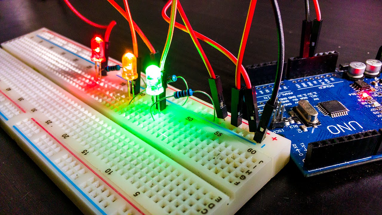
1. LED Blinking Circuit: One of the most common projects is a simple LED blinking circuit. By connecting an LED, a current-limiting resistor, and a microcontroller or an Arduino board, you can create a circuit that makes the LED blink at a specific time interval. This project introduces the basics of digital output and control signals.
2. Temperature Sensor Circuit: Using a temperature sensor, such as a TMP36 or a DS18B20, you can build a circuit that measures ambient temperature and displays the results. By connecting the temperature sensor to an Arduino or a microcontroller, you can convert the analog temperature reading into a digital output, which can be displayed on an LCD or transmitted wirelessly.
3. Audio Amplifier Circuit: Breadboards can also accommodate audio circuits, such as small audio amplifiers. By connecting an audio source, an amplifier IC (such as the LM386), and a speaker, you can create a simple audio amplifier circuit that allows you to amplify and play sound from different audio sources, like a smartphone or MP3 player.
4. Logic Gates Circuit: Breadboards are ideal for building logic gates and digital circuits. By using logic gate ICs, such as the 7400 series, you can create circuits that perform logical operations, such as AND, OR, and XOR. These circuits are a fundamental building block for more complex digital systems and can be used in projects like binary calculators or digital displays.
5. Motor Control Circuit: With the help of an H-bridge circuit and a microcontroller, you can build a motor control circuit on a breadboard. This allows you to control the speed and direction of a DC motor. This type of circuit is commonly used in robotics projects, automated systems, and home automation applications.
These examples represent just a fraction of the circuits that can be built on a breadboard. From basic experiments to advanced projects, breadboards provide a platform for learning and prototyping various electronic circuits. They allow for quick modifications and iterations, making it easier to test and refine your designs before moving to more permanent soldered solutions.