
The Importance of Testing Continuity
Testing continuity is a crucial step in electrical troubleshooting and maintenance. It ensures that there is a complete path for electrical current to flow through a circuit, without any breaks or interruptions. By identifying and fixing continuity issues, you can prevent potential electrical failures, malfunctions, and even hazards.
Continuity testing is especially important in situations where the flow of electricity is critical, such as in the operation of safety systems, equipment, and appliances. It helps you identify faulty components, damaged wires, loose connections, or blown fuses. By addressing these issues promptly, you can prevent potential damage to electrical systems and reduce the risk of electrical accidents or fires.
Another significant reason to test continuity is to ensure the effectiveness of electrical grounding. Grounding is essential for dissipating excess electrical energy and preventing electrical shock. By testing continuity, you can verify that the grounding path is intact, providing a safe route for electricity to flow in the event of a short circuit or electrical surge.
Additionally, continuity testing is useful during the installation and maintenance of electrical systems. It helps validate proper wiring connections and ensure that all components are functioning as intended. It is particularly important when working with complex and intricate circuits, where even minor breaks in continuity can cause significant problems.
By regularly testing continuity, you can also detect potential future issues. It allows you to identify weak points in the electrical system that might eventually lead to failures or malfunctions. By addressing these weak points preemptively, you can extend the lifespan of your electrical components, enhance system performance, and save both time and money on costly repairs down the line.
What is Continuity?
Continuity is a fundamental concept in electrical circuits that refers to the unobstructed flow of electrical current from one point to another. It measures the level of connectivity between various components and conductors in a circuit. A circuit with good continuity allows electricity to flow smoothly, while a circuit with poor continuity exhibits interruptions or breaks in the electrical path.
At its core, continuity testing involves verifying the presence of a complete electrical pathway between two points. This is accomplished by checking for continuous conductive paths, such as wires, connectors, switches, or components. If there is continuity, it indicates that there are no breaks, damage, or loose connections in the circuit.
One common method for testing continuity is by using a digital multimeter. The multimeter measures the resistance between two points in a circuit. If there is continuity, the resistance reading will be very low or close to zero, indicating a strong connection. On the other hand, if there is a break in continuity, the resistance reading will be high, indicating an interruption or a weak connection.
Continuity is essential for the proper functioning of electrical devices and systems. Without a complete pathway for electric current, devices may not power on, motors might not run, or circuitry may malfunction. By testing continuity, you can detect and resolve issues that could impair the performance or safety of electrical systems.
Moreover, continuity plays a vital role in the troubleshooting process. When faced with electrical problems, continuity testing allows you to isolate faulty components or sections within a circuit. By systematically testing various points and comparing the results, you can trace the source of the problem and take appropriate measures to rectify it.
It is important to note that continuity testing is not limited to just identifying breaks in a circuit. It can also be used to verify the absence of continuity in specific situations, such as ensuring there is no electrical connection between certain points, or confirming the isolation of different circuits or conductors.
How Does a Digital Multimeter Work?
A digital multimeter is a versatile and essential tool for testing continuity and measuring electrical parameters. It combines several functions into a single device, including voltage measurement, current measurement, and resistance measurement. Understanding how a digital multimeter works is crucial for accurate continuity testing and other electrical measurements.
At its core, a digital multimeter works by utilizing precision electronic components to measure different electrical quantities. It consists of a display screen, a knob or buttons for selecting the desired measurement function, and two or more probes for making electrical connections.
When testing continuity, the digital multimeter sends a small amount of current through the circuit being tested. It then measures the resistance encountered by the current as it flows through the circuit. This measurement is then displayed on the screen as a numerical value.
The digital multimeter uses the principle of Ohm’s Law to measure resistance. Ohm’s Law states that the current flowing through a conductor is directly proportional to the voltage across the conductor and inversely proportional to the resistance of the conductor. By applying a known voltage and measuring the resulting current, the digital multimeter can calculate the resistance of the circuit being tested.
In continuity testing mode, the digital multimeter typically emits an audible beep or displays a specific symbol on the screen when there is continuity detected. This simplifies the process of identifying whether a circuit has a continuous pathway or if there is a break in the continuity.
Most digital multimeters also have different ranges or settings for continuity testing to accommodate various circuits and resistance values. The user can select the appropriate range based on the expected resistance of the circuit being tested. This ensures accurate readings and prevents potential damage to the multimeter from excessive current.
It is worth noting that digital multimeters require proper calibration and periodic maintenance to ensure accurate measurements. Calibration involves adjusting the internal components of the multimeter to account for any deviations from the standard values. Regular calibration ensures that the readings provided by the digital multimeter are precise and reliable.
Overall, a digital multimeter is a powerful tool that simplifies and enhances the process of testing continuity and other electrical measurements. Its versatility and ease of use make it indispensable for both professional electricians and hobbyists working with electrical circuits.
Preparing Your Digital Multimeter
Before you begin testing continuity using a digital multimeter, it’s important to ensure that your multimeter is properly prepared. Taking a few simple steps to set up your digital multimeter will help ensure accurate and reliable readings, as well as protect the multimeter from any potential damage.
Here are some essential steps to prepare your digital multimeter for continuity testing:
Step 1: Familiarize yourself with the multimeter: Read the user manual and understand the different functions, settings, and buttons on your digital multimeter. This will enable you to navigate the device easily and select the appropriate settings for continuity testing.
Step 2: Check the batteries: Ensure that your digital multimeter has fresh and properly functioning batteries. Low battery levels can affect the accuracy of the readings. If necessary, replace the batteries with new ones to ensure reliable performance.
Step 3: Set the meter to continuity mode: Most digital multimeters have a dedicated continuity mode or a setting that allows you to test continuity. Select this mode or setting on your multimeter using the knob or buttons provided. The continuity mode is often denoted by a symbol resembling sound waves or a diode.
Step 4: Set the range: Select the appropriate range for continuity testing on your multimeter. The range setting should encompass the expected resistance values in the circuit you are testing. If you are unsure, start with the highest range and work your way down until you obtain a reading within the desired range.
Step 5: Connect the test leads: Attach the test leads to the correct ports on your digital multimeter. The black lead, typically referred to as the common lead or ground lead, should be connected to the common port. The red lead, often referred to as the positive lead or voltage/current lead, should be connected to the port marked for continuity testing.
Step 6: Verify functionality: To ensure your digital multimeter is functioning properly, perform a quick test. Touch the test leads together and check if the multimeter displays a reading close to zero or emits an audible beep. This confirms that the continuity feature is working correctly.
By following these steps, you can ensure that your digital multimeter is properly prepared for continuity testing. Taking the time to properly set up your multimeter will save you from potential troubleshooting headaches and ensure accurate results during your continuity testing process.
Step-by-Step Guide to Testing Continuity
Testing continuity using a digital multimeter is a straightforward process that involves a few simple steps. Follow this step-by-step guide to ensure accurate continuity testing results:
Step 1: Safety First: Before you start, ensure that the power to the circuit or device you are testing is turned off. This prevents any potential accidents or damage to the multimeter.
Step 2: Set Up: Prepare your digital multimeter by following the instructions outlined in the “Preparing Your Digital Multimeter” section. Ensure the multimeter is set to the continuity mode and the appropriate range is selected.
Step 3: Connect the Test Leads: Connect the black (common) test lead to the common port and the red (positive) test lead to the port designated for continuity testing. Make sure the probes are securely attached to the multimeter and the ends are in good condition.
Step 4: Touch the Test Leads: With the circuit or component you want to test in mind, touch the test leads together. This establishes a baseline reading for continuity. Your multimeter should indicate a low resistance reading or emit a continuous beep to confirm continuity.
Step 5: Separate the Test Leads: Now, disconnect the test leads and separate them. You’re ready to begin testing the continuity of the circuit or component.
Step 6: Place the Test Leads: Take the test leads and place them on the two points in the circuit or component you want to test for continuity. Ensure that the test leads make good contact and that there are no obstructions that could interfere with the measurement.
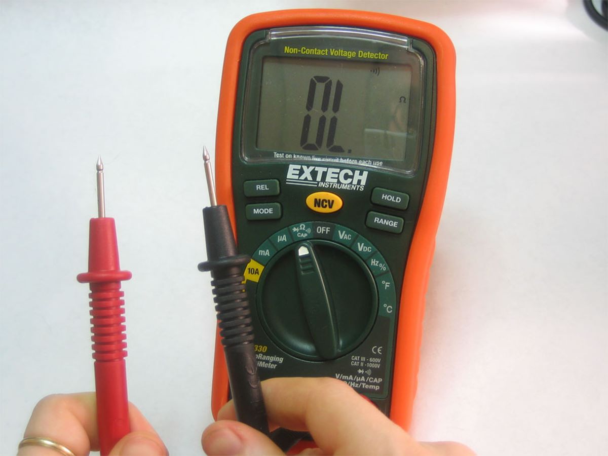
Step 7: Observe the Reading: Look at the digital display on your multimeter or listen for the audible beep. If the resistance reading is near zero or the beep is continuous, it indicates that there is continuity in the circuit or component being tested. If there is no reading or the multimeter displays a high resistance value, there is a break in the continuity.
Step 8: Identify and Fix Issues: If you discover a break in continuity, it’s essential to locate and rectify the issue. Inspect the wiring, connections, and components for any signs of damage or loose connections. Repair or replace any faulty components or wiring to restore continuity.
Step 9: Repeat and Verify: If necessary, repeat the continuity testing at different points in the circuit or other components to ensure a comprehensive assessment of continuity.
By following these step-by-step instructions, you can perform accurate continuity testing using a digital multimeter. This process helps identify any breaks or interruptions in a circuit, allowing you to address and resolve issues promptly.
Common Mistakes to Avoid
While testing continuity with a digital multimeter is a relatively straightforward process, there are some common mistakes that you should avoid to ensure accurate results and prevent potential damage to the multimeter or the circuit being tested:
Mistake 1: Forgetting to disconnect power: Before performing continuity testing, always make sure to turn off the power to the circuit or device. Failing to do so can result in electric shock or damage to the multimeter.
Mistake 2: Using the wrong mode or range: Double-check that you have selected the correct continuity mode and range on your digital multimeter. Using the incorrect settings can lead to inaccurate readings or damage to the multimeter.
Mistake 3: Poor contact with the test leads: Ensure that the test leads make solid and secure contact with the points being tested. Loose or inadequate contact can result in unreliable continuity readings.
Mistake 4: Testing a live circuit: Continuity testing should only be conducted on de-energized circuits or devices. Testing a live circuit can be dangerous and may cause significant damage to the multimeter.
Mistake 5: Neglecting to check test leads and probes: Regularly inspect the test leads and probes for any signs of damage, such as fraying or wear. Damaged leads can compromise the accuracy of the continuity readings.
Mistake 6: Rushing the testing process: Take your time to ensure proper connections and reliable readings. Rushing through the process can lead to mistakes or overlooking potential continuity issues.
Mistake 7: Overloading the multimeter: Avoid exceeding the current or voltage limits of your multimeter during continuity testing. Excessive current or voltage can damage the multimeter and render it unusable.
Mistake 8: Not repeating the test: It’s crucial to repeat the continuity testing at multiple points in the circuit or on different components to ensure a comprehensive assessment. This helps identify any intermittent continuity issues that may not be immediately apparent.
Mistake 9: Ignoring safety precautions: Always prioritize safety when working with electricity. Wear appropriate personal protective equipment (PPE) and follow safety guidelines to minimize the risk of electrical shock or accidents.
By avoiding these common mistakes, you can ensure accurate and reliable continuity testing results while preserving the integrity of your digital multimeter and protecting yourself from potential hazards.
Tips for Accurate Continuity Testing
To obtain accurate and reliable continuity testing results using a digital multimeter, consider the following tips:
Tip 1: Ensure a stable testing environment: Perform continuity testing in a stable and well-lit area. Minimize any external factors that could interfere with the test, such as electromagnetic interference or excessive noise.
Tip 2: Clean the test points: Before conducting continuity testing, clean the test points or contact surfaces to remove any dirt, oxidation, or corrosion. This ensures better conductivity and more accurate readings.
Tip 3: Use the appropriate test leads: Depending on the specific circuit or component being tested, you may need to use specialty test leads. These leads are designed to provide a more secure and specialized connection, enhancing the accuracy of the continuity testing.
Tip 4: Check for zero resistance: Before testing continuity, measure the resistance reading while touching the test leads together. It should display near-zero resistance or emit a continuous beep. If not, investigate and address any potential issues with the test leads or multimeter.
Tip 5: Use back-probing techniques: In certain cases, it may be challenging to access specific points in a circuit for continuity testing. You can use back-probing techniques, where you insert the test leads into the connectors or terminals from the rear, to obtain more accurate continuity readings.
Tip 6: Consistently interpret readings: Familiarize yourself with the readings your digital multimeter provides for continuity testing. Document the normal range of resistance values for various circuits and components, as this will assist in quick and accurate interpretation of the readings.
Tip 7: Confirm the expected results: Before performing continuity tests, verify the expected readings for the specific circuit or component being tested. Consult equipment manuals or seek professional guidance to understand the expected continuity values.
Tip 8: Test adjacent points: If you suspect a break in continuity, test adjacent points within the circuit as well. This can help pinpoint the exact location of the issue and ensure that you identify the correct problematic area.
Tip 9: Repeat tests for accuracy: Repeat the continuity tests multiple times to ensure accurate and consistent results. Conducting the tests at different times can help identify intermittent continuity issues that may not be detected during a single test.
Tip 10: Follow safety precautions: Always prioritize safety when working with electrical circuits. Wear appropriate personal protective equipment (PPE), adhere to safety guidelines, and ensure proper insulation and grounding to minimize the risk of electrical shock or accidents.
By following these tips, you can enhance the accuracy and reliability of continuity testing using a digital multimeter. This will enable you to quickly identify and address any continuity issues in circuits or components, ensuring the proper functioning and safety of electrical systems.
When to Use Continuity Testing
Continuity testing is a valuable tool in various situations when troubleshooting electrical circuits or components. Understanding when to use continuity testing can help you pinpoint electrical issues and ensure proper functionality. Here are some common scenarios where continuity testing is useful:
1. Checking for faulty connections: Continuity testing is essential when verifying the integrity of electrical connections. By testing continuity between different points in a circuit or between wires and connectors, you can identify faulty or loose connections that may cause intermittent or complete loss of electrical flow.
2. Troubleshooting broken circuits: When a circuit is not functioning as expected, continuity testing can help locate breaks or interruptions in the wiring. By testing continuity at various points along the circuit, you can identify the specific location of the break and take appropriate measures to repair or replace the damaged section.
3. Assessing component functionality: Continuity testing is useful in checking the functionality of individual components within a circuit. By testing continuity across the terminals of components such as switches, relays, fuses, or sensors, you can determine if they are functioning correctly or if they need to be replaced.
4. Verifying continuity in cables and harnesses: Continuity testing is commonly employed in testing cables, wires, and harnesses for continuity. This allows you to ensure that there are no breaks, open circuits, or short circuits in the wiring and that the electrical signals can flow unhindered from one end to another.
5. Checking for proper grounding: Continuity testing is crucial for validating the effectiveness of grounding in electrical systems. By testing continuity between the ground terminal and various points in the system, you can ensure the existence of a proper grounding path, which is essential for dissipating excess electrical energy and preventing electrical shock hazards.
6. Detecting damaged or defective equipment: Continuity testing is valuable in identifying damaged or defective equipment. By testing continuity on the connections and components of equipment, you can determine if any internal damage or faults are disrupting the flow of electricity and affecting the device’s functionality.
7. Inspecting circuit board traces: Continuity testing allows you to check the continuity of traces on a circuit board to ensure that they are not damaged, broken, or shorted. This is particularly crucial during repair or diagnostic work on electronic devices.
8. Preparing new installations: Continuity testing is vital during the installation of new electrical systems or components. It helps verify that the wiring and connections are properly established and that there are no breaks or faults before energizing the circuit.
By utilizing continuity testing in these situations, you can identify and resolve electrical issues promptly, ensuring the reliability, safety, and efficiency of electrical systems and components.
Testing Continuity in Various Electrical Components
Continuity testing is a versatile technique that can be applied to various electrical components to ensure proper functionality. By testing continuity in specific components, you can verify their integrity and identify any potential issues. Here are some examples of how to test continuity in different electrical components:
1. Switches: To test continuity in a switch, set your multimeter to the continuity mode and touch the probes to the terminals of the switch. Activate the switch into its closed position. If there is continuity, the multimeter will indicate a low resistance or emit a continuous beep. If there is no continuity, the multimeter will display a high resistance or remain silent, indicating a faulty switch that needs to be replaced.
2. Fuses: When testing the continuity of a fuse, remove it from the circuit and set your multimeter to the continuity mode. Touch the probes to either end of the fuse. If there is continuity, the multimeter will display a low resistance or emit a continuous beep. If there is no continuity, the multimeter will show a high resistance or remain silent, indicating a blown fuse that needs to be replaced.
3. Relays: To test continuity in a relay, set your multimeter to the continuity mode and touch the probes to the appropriate terminals of the relay. Activate the relay by applying the input signal or voltage. If there is continuity, the multimeter will indicate a low resistance or emit a continuous beep. If there is no continuity, the multimeter will display a high resistance or remain silent, indicating a faulty relay that needs to be replaced.
4. Capacitors: Continuity testing is not suitable for testing capacitors, as capacitors store and release energy based on their capacitance value, rather than allowing constant electrical flow. To test capacitors, it is best to use a specialized capacitance meter or an oscilloscope.
5. Diodes: When testing continuity in diodes, set your multimeter to the diode mode. Touch the probes to the anode and cathode terminals of the diode. If the diode is forward-biased, indicating proper functionality, the multimeter will display a low resistance reading or emit a continuous beep. If the diode is reverse-biased, indicating a faulty diode, the multimeter will show a high resistance reading or remain silent.
6. Motors and coils: To test continuity in motors, coils, or inductors, set your multimeter to the continuity mode and touch the probes to the individual coil windings or terminals. If there is continuity, the multimeter will indicate a low resistance or emit a continuous beep. If there is no continuity, the multimeter will display a high resistance or remain silent, indicating a break or fault in the winding.
7. Wiring and connectors: Continuity testing is particularly useful for verifying the integrity of wiring and connectors. Touch the probes to both ends of the wire or across the terminals of the connector. If there is continuity, the multimeter will indicate a low resistance or emit a continuous beep. If there is no continuity, the multimeter will display a high resistance or remain silent, indicating a break or poor connection that needs attention.
8. PCB traces and circuit boards: When testing continuity in printed circuit board (PCB) traces or circuit boards, set your multimeter to the continuity mode and touch the probes at different points along the traces or across the desired connections. If there is continuity, the multimeter will indicate a low resistance or emit a continuous beep. If there is no continuity, the multimeter will show a high resistance or remain silent, indicating a break or damaged trace that requires repair.
By appropriately applying continuity testing to various electrical components, you can identify faults, ensure proper functionality, and maintain the reliability and efficiency of electrical systems.