
The Basics of Inductors
Inductors are fundamental components in electronics that play a crucial role in many circuits and systems. They are passive components, meaning they do not require an external power source to function. Instead, they rely on the phenomenon of electromagnetic induction.
At its core, an inductor is a coil of wire wound around a core material, typically made of ferrite or iron. The number of turns in the wire and the core material determine the inductor’s inductance, which is a measure of its ability to store energy in a magnetic field.
When an electric current flows through the inductor, it generates a magnetic field around the coil according to Ampere’s law. This magnetic field stores energy within the inductor. The inductance value determines how effectively the inductor can store this energy. The unit of inductance is the Henry (H), named after the physicist Joseph Henry.
The key property of an inductor is its ability to oppose changes in current. According to Faraday’s law of electromagnetic induction, when the current through an inductor changes, it induces a voltage across the inductor that opposes this change. This voltage is known as back EMF (electromotive force).
By opposing changes in current, inductors play a crucial role in filtering and smoothing the flow of electricity. They are frequently used in power supplies and analog circuits to block unwanted fluctuations, or noise, in the current and ensure a stable output. Additionally, inductors are essential in energy storage applications, such as inductors used in power factor correction circuits.
It is important to note that inductors have some inherent characteristics that need to be considered in circuit design. Inductors have series resistance, known as the DC resistance (DCR), which affects their overall performance. They also have a self-resonant frequency, beyond which their inductive properties start to degrade.
In summary, inductors are passive components that rely on electromagnetic induction to store energy in a magnetic field. They play a vital role in regulating current flow, filtering out noise, and storing energy in various electronic applications.
Next, we will delve deeper into how inductors work and explore their construction and symbols.
How Inductors Work
Inductors are fascinating components that harness the principles of electromagnetism to perform their functions. Understanding how inductors work is essential for designing and analyzing electronic circuits.
As mentioned earlier, inductors store energy in a magnetic field. When an electric current passes through an inductor, a magnetic field is generated around the coil. The strength of this magnetic field depends on the number of turns in the coil and the current flowing through it.
Inductors have a unique property called self-inductance or simply inductance, which is represented by the symbol ‘L.’ Inductance is a measure of how much magnetic flux is produced for a given current. The unit of inductance is the Henry (H).
According to Faraday’s law of electromagnetic induction, when the current through an inductor changes, it induces a voltage across the inductor. This voltage, called back EMF, opposes the change in current. Essentially, an inductor resists changes in current flow by storing and releasing energy. This property allows inductors to perform various functions in electronic circuits.
One of the primary applications of inductors is in filtering and smoothing the flow of electricity. Inductors are commonly used in conjunction with capacitors to create low pass, high pass, or bandpass filters. The inductor’s ability to impede changes in current helps remove noise and unwanted fluctuations, ensuring a more stable output.
Furthermore, inductors are essential in energy storage applications. When a current flows through an inductor, it stores energy in the magnetic field. This stored energy can be released back into the circuit when the current changes or is interrupted. This property is utilized in various applications like transformers, magnetic coils, and inductor-based energy storage devices.
Inductors also play a vital role in inductive loads, such as motors and solenoids. These devices use the magnetic field produced by inductors to perform mechanical work, converting electrical energy into mechanical energy.
Inductor Construction
Inductors are typically constructed using a coil of wire wound around a core material. The inductor’s construction influences its performance and characteristics.
The coil of wire is the most crucial component of an inductor. It can be made of various materials, including copper, aluminum, or other conductive alloys. The wire is carefully wound into a helical shape to create multiple turns. The number of turns determines the inductance value of the inductor; more turns result in higher inductance.
The core material used in an inductor can greatly affect its performance. Common core materials include ferrite and iron. Ferrite cores are made of a ceramic material with excellent magnetic properties. They are used in high-frequency applications due to their ability to handle high flux density. Iron cores, on the other hand, are suitable for low-frequency applications because of their high permeability.
The core serves to concentrate and guide the magnetic field generated by the current flowing through the coil. It enhances the inductance of the inductor and allows for better energy storage. The choice of core material depends on the specific application and desired performance characteristics.
Inductors may be categorized into two main types based on their core construction: air core and magnetic core inductors. Air core inductors have no core material and rely solely on the wire coil for their magnetic properties. They are used in applications where high-frequency operation or minimal magnetic interference is required, such as radio frequency circuits and telecommunications.
Magnetic core inductors, as the name suggests, use a core material to enhance their magnetic properties. This type of inductor is more common and finds applications in power electronics, transformers, and inductive loads. The choice of core material also affects the inductor’s saturation current, temperature stability, and frequency response.
Inductor Symbol and Representation
In circuit diagrams and schematic drawings, inductors are represented by a specific symbol that helps to identify them and understand their role in the circuit.
The symbol for an inductor consists of two parallel lines, sometimes with curved or straight ends, as shown below:

It is important to note that the position and orientation of the inductor symbol do not affect its functionality; they are used for visual clarity and ease of understanding in the circuit diagram.
Inductor symbols can also include additional markings to represent specific characteristics or specifications of the inductor. For example, an arrow may be used to indicate the direction of winding, denoting the polarity of the inductor.
The inductor symbol is often accompanied by a label or designation, indicating the inductor’s value or inductance in Henry (H). This value is represented by the letter ‘L’ followed by a subscript or numerical value. For example, L1 or L100uH indicates an inductor with an inductance of 1 Henry or 100 microhenries, respectively.
It is worth noting that in some cases, different types of inductors may have alternative symbols to represent their specific functions or characteristics. For instance, variable inductors may be represented by a rectangle with an arrow pointing towards the coil to indicate adjustability.
Overall, the inductor symbol and representation in circuit diagrams provide a standardized way to identify and understand the role of inductors in electronic circuits. They convey important information about the inductor’s orientation, winding direction, and value, allowing engineers and technicians to analyze and design circuits with precision.
Inductance and Units
Inductance is a fundamental property of inductors that measures their ability to store energy in a magnetic field. It is a key parameter that determines the behavior and characteristics of an inductor.
The unit of inductance is the Henry (H), named after the renowned scientist Joseph Henry. One Henry is defined as the inductance of an inductor that induces an electromotive force of one volt when the current through it changes at a rate of one ampere per second.
However, in practice, inductance values are often much smaller than one Henry, and therefore, subunits and prefixes are commonly used to represent different orders of magnitude. The following are some commonly used units and prefixes for inductance:
- Millihenry (mH): One millihenry is equal to one thousandth of a Henry. It is denoted by the prefix ‘m.’, for example, 2.5 mH.
- Microhenry (µH): One microhenry is equal to one millionth of a Henry. It is denoted by the prefix ‘µ’ or ‘u’, for example, 500 µH or 500 uH.
- Nanohenry (nH): One nanohenry is equal to one billionth of a Henry. It is denoted by the prefix ‘n.’, for example, 100 nH.
- Picohenry (pH): One picohenry is equal to one trillionth of a Henry. It is denoted by the prefix ‘p.’, for example, 50 pH.
These subunits allow for more convenient representation and expression of inductance values within different ranges. Engineers and technicians often choose the appropriate unit based on the specific requirements of the circuit design or application.
Inductance values are determined by various factors, including the number of turns in the coil, the core material, the physical dimensions of the inductor, and the magnetic permeability of the core. Increasing the number of turns or selecting a core material with higher permeability generally results in higher inductance.
Accurate measurement and selection of inductance are crucial for designing and analyzing electronic circuits. Specialized instruments like inductance meters or LC meters are often used to measure the inductance of an inductor with precision.
Inductor Impedance
In electronic circuits, inductors not only store energy but also introduce impedance to the flow of alternating current (AC). Inductor impedance is an essential concept to understand when analyzing and designing circuits involving inductors.
Impedance, denoted by ‘Z,’ is a measure of the opposition to the flow of AC current in a component or circuit. It combines the resistance and reactance of the component. For inductors, impedance is primarily determined by their inductive reactance.
Reactance is the opposition to the flow of AC current caused by the inductor’s inductance. Inductive reactance, denoted by ‘XL,’ is directly proportional to the inductance (L) of the inductor and the frequency (f) of the AC current. The formula for inductive reactance is:
XL = 2πfL
Where:
- XL is the inductive reactance in ohms (Ω)
- f is the frequency of the AC current in hertz (Hz)
- L is the inductance of the inductor in Henrys (H)
- π (pi) is a mathematical constant approximately equal to 3.14159
The impedance of an inductor (ZL) is given by the formula:
ZL = jXL
Where:
- ZL is the impedance of the inductor in ohms (Ω)
- j is the imaginary unit (√-1)
- XL is the inductive reactance
Since the reactance of an inductor is frequency-dependent, the impedance of an inductor also varies with the frequency of the AC current passing through it. As the frequency increases, the inductive reactance increases, resulting in higher impedance for the inductor.
It is important to note that inductors exhibit purely reactive behavior in ideal conditions since they have no resistance. However, in real-world scenarios, inductors have some resistance known as the DC resistance (DCR) due to the wire used in their construction. The resistance component adds to the total impedance of the inductor.
The impedance of an inductor affects the overall behavior and performance of the circuit. It can limit the flow of AC current, cause phase shifts, and affect the power transfer efficiency of the circuit. Understanding and considering inductor impedance is crucial when designing circuits involving inductors, especially in AC applications like filters, power supplies, and audio amplifiers.
Inductor Types and Applications
Inductors come in various types and designs, each suited for specific applications based on their characteristics and performance. Understanding the different types of inductors is essential when selecting the right component for a particular circuit or system.
Here are some common types of inductors and their applications:
- Air Core Inductors: These inductors do not have a core material and are made up of a coil of wire. They are primarily used in high-frequency applications such as radio frequency circuits, telecommunications, and inductors for speakers.
- Ferrite Core Inductors: These inductors include a ferrite core material that enhances their magnetic properties. They are widely used in power electronics, power supplies, and high-frequency circuits due to their ability to handle high flux density. Ferrite core inductors provide efficient energy storage and facilitate noise filtering.
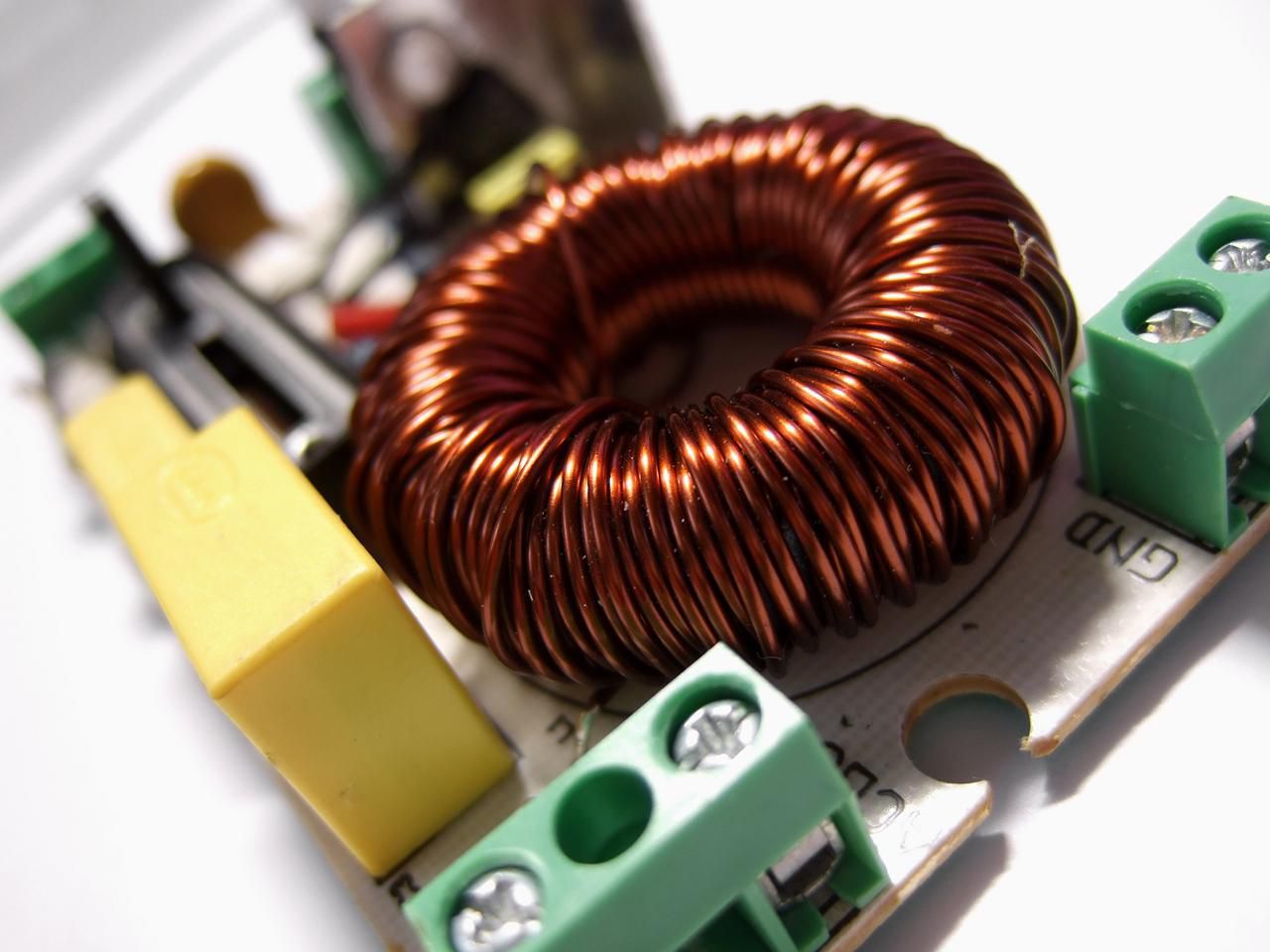
- Toroidal Inductors: These inductors feature a doughnut-shaped core. Toroidal inductors offer low magnetic interference and high inductance per unit volume. They are commonly used in power supplies, audio circuits, and electromagnetic interference (EMI) filters. Their compact and efficient design makes them suitable for applications in limited spaces.
- SMD Inductors: Surface mount device (SMD) inductors are designed for use on printed circuit boards (PCBs). These inductors come in small package sizes and are suitable for compact electronic devices such as smartphones, tablets, and laptops. SMD inductors find applications in power management, RF circuits, and digital signal processing.
- Variable Inductors: These inductors are designed to have adjustable inductance. They are utilized in applications where variable or tunable inductance is required, such as antennas, oscillators, and RF filters. Variable inductors often use a movable core or a tapped winding to alter the inductance value.
Along with these types, specialized inductors such as coupled inductors, power inductors, and choke coils are used in specific applications. Coupled inductors are used in transformers and voltage regulation circuits. Power inductors are designed to handle higher currents and are commonly found in DC-DC converters, motor drives, and power supplies. Choke coils are used to filter out noise, suppress unwanted signals, and provide impedance in power supply circuits.
Inductors find applications across a broad range of industries and electronic devices. Some common applications of inductors include power supplies, filters, oscillators, transformers, motor drives, RF circuits, and audio amplifiers. Inductors play a crucial role in energy storage, noise reduction, signal conditioning, and frequency selection in these applications.
Choosing the right type of inductor is crucial to ensure optimal performance and efficiency in a specific circuit or system. Factors such as inductance value, current rating, core material, and physical size should be considered when selecting an inductor for a particular application.
Inductor Energy Storage
One of the key functions of inductors is to store energy in the form of a magnetic field. This energy storage property of inductors is utilized in various electronic applications for power transfer, energy conversion, and voltage regulation.
When a current flows through an inductor, it generates a magnetic field around the coil according to Ampere’s law. This magnetic field stores energy, which can be released back into the circuit when the current changes or is interrupted.
The energy stored in an inductor is given by the equation:
E = 0.5 * L * I^2
Where:
- E is the energy stored in joules (J)
- L is the inductance of the inductor in Henrys (H)
- I is the current flowing through the inductor in amperes (A)
This equation shows that the energy stored in an inductor is directly proportional to the square of the current and the inductance value. Therefore, increasing the current or the inductance of an inductor can significantly increase its energy storage capacity.
Inductor energy storage is utilized in a wide range of applications. One common application is in power supplies, where inductors are used in combination with capacitors to create energy storage and filtering circuits. Inductors store energy during the ‘on’ time of a switching circuit, and then release the energy during the ‘off’ time to maintain a continuous and regulated output.
Inductors are also used in energy conversion systems, such as inductors in DC-DC converters or inverters. In these applications, the inductor stores energy during certain parts of the conversion cycle and releases it during other parts, ensuring efficient energy transfer and regulation.
Another application of inductor energy storage is in voltage regulation circuits. Inductors are used in voltage regulators, both linear and switching, to store energy and provide a stable output voltage despite fluctuations in the input voltage or load conditions.
Inductor energy storage is also essential in applications such as flyback transformers, where the energy stored in the inductor’s magnetic field is transferred to other circuits through mutual coupling for voltage regulation or isolation purposes.
Overall, inductor energy storage plays a vital role in various electronic applications, particularly in power supplies, energy conversion, and voltage regulation. The ability of inductors to store and release energy in the form of a magnetic field contributes to the efficient operation and stability of these systems.
Inductor Circuit Analysis
Circuit analysis involving inductors requires a thorough understanding of their characteristics and behavior. Analyzing inductor circuits involves considering the inductor’s impedance, current changes over time, and energy storage properties.
One of the key factors in inductor circuit analysis is the inductor’s impedance, which is frequency-dependent. The impedance of an inductor, denoted by ‘ZL,’ is determined by its inductive reactance (XL). As the frequency of the alternating current (AC) passing through the inductor increases, the inductive reactance and impedance also increase accordingly.
When analyzing AC circuits with inductors, it is necessary to consider both the resistive and reactive components of the circuit. The total impedance of the circuit, denoted by ‘Z,’ is the vector sum of the resistive impedance (R) and the inductive impedance (XL):
Z = R + jXL
Where ‘j’ represents the imaginary unit (√-1).
Another important aspect of inductor circuit analysis is understanding the behavior of inductors during current changes. According to Faraday’s law of electromagnetic induction, when the current through an inductor changes, it induces a voltage across the inductor that opposes this change, known as back electromotive force (EMF).
This property of inductors leads to a time delay in the current response. When a DC voltage is suddenly applied to an inductor, the current does not reach its maximum value instantaneously. Instead, it gradually increases over time, following an exponential growth curve determined by the inductance and the resistance of the circuit.
Furthermore, when the current through an inductor is interrupted or decreases, the stored energy in the inductor’s magnetic field is released, causing a voltage spike known as a flyback or back EMF. These voltage spikes can potentially damage components in the circuit, and proper consideration must be given to protect against them, especially in circuits with inductive loads.
Inductor circuit analysis also involves understanding the energy transfer and storage properties of inductors. As mentioned earlier, inductors store energy in their magnetic fields. This stored energy can be used to provide continuous power supply during transient periods or to regulate voltage levels in certain applications. Analyzing the energy storage and release patterns of inductors is crucial for designing efficient and reliable circuits.
Overall, inductor circuit analysis involves considering the impedance, current behavior, and energy storage properties of inductors. Through careful analysis and calculations, engineers and technicians can design and optimize circuits incorporating inductors for various applications.
Inductor Characteristics and Specifications
Inductor characteristics and specifications provide important information about the performance and behavior of an inductor. Understanding these specifications is crucial for selecting the right inductor for a specific application and ensuring the overall functionality of the circuit or system.
Some of the key characteristics and specifications of inductors include:
- Inductance: Inductance, denoted by ‘L,’ is the fundamental characteristic of an inductor. It represents the ability of an inductor to store energy in a magnetic field. Inductance is typically measured in Henry (H), with common values ranging from microhenries (µH) to millihenries (mH) or higher.
- Tolerance: Tolerance indicates the acceptable deviation from the stated inductance value. It is specified as a percentage and represents the maximum allowable difference between the actual inductance and the nominal inductance value. Typical tolerance values range from ±5% to ±20%.
- DC Resistance (DCR): The DC resistance of an inductor, denoted by ‘DCR,’ refers to the resistance encountered by direct current (DC) flowing through the coil. It is caused by the wire used in the inductor’s construction. DCR is an important specification to consider as it affects the inductor’s power dissipation and overall performance.
- Current Rating: The current rating of an inductor specifies the maximum continuous current that the inductor can handle without exceeding its temperature limits. It is important to select an inductor that can handle the maximum current required by the specific application to prevent overheating and potential damage.
- Saturation Current: Saturation current is the maximum current at which the inductor can operate without losing its inductance or entering a state of saturation. Operating an inductor above its saturation current may result in distortion of the inductance value or loss of inductive properties.
- Self-Resonant Frequency: The self-resonant frequency (SRF) is the frequency at which the inductor’s inductive reactance is equal to its capacitive reactance, resulting in resonance. Above the SRF, the inductor starts to exhibit capacitive characteristics instead of inductive behavior.
Other specifications like temperature coefficient, operating temperature range, physical dimensions, and insulation class are also important considerations when selecting an inductor for a specific application. These specifications ensure the inductor’s compatibility with the circuit requirements, its ability to withstand environmental conditions, and its overall reliability.
Manufacturers provide detailed datasheets for each inductor model, which outline the specific characteristics and specifications. It is important to refer to these datasheets to understand the inductor’s performance limitations, electrical parameters, and any special considerations for proper operation.
Inductor Selection and Sizing
Choosing the right inductor for a specific application involves considering various factors, such as the desired inductance value, current requirements, frequency range, and physical size constraints. Proper selection and sizing of the inductor are crucial to ensure the successful functioning of the circuit or system.
Here are some key steps to follow in the process of inductor selection and sizing:
- Determine the required inductance: Start by determining the desired inductance value based on the circuit’s requirements. Consider factors such as the target frequency range, level of noise to be filtered, or energy storage requirements.
- Consider the current requirements: Evaluate the maximum current that the inductor will need to handle. Ensure that the selected inductor has a current rating higher than the maximum current to prevent overheating or saturation.
- Account for the frequency range: Consider the frequency range of the circuit or system. Select an inductor with an appropriate self-resonant frequency (SRF) above the operating frequency to ensure optimal performance. At frequencies close to the SRF, the inductor may exhibit undesirable capacitive characteristics.
- Account for physical size constraints: Assess the available space for the inductor in the PCB layout or the physical housing. Consider the size and footprint of the inductor to ensure a proper fit within the constraints.
- Review datasheets: Consult the datasheets provided by the manufacturer for the selected inductor models. Review the inductance tolerance, DC resistance (DCR), current rating, and other specifications to ensure they meet the requirements of the application. Pay attention to any temperature derating or environmental factors mentioned in the datasheets.
- Consider cost and availability: Evaluate the cost and availability of the selected inductors. Determine if the inductors are readily available in the required quantities and if they fit within the project’s budget constraints.
- Simulation and testing: Where possible, utilize circuit simulation tools or breadboard prototypes to evaluate the inductor’s performance within the specific circuit or system. This helps validate the chosen inductor’s suitability and performance before final implementation.
It is essential to note that inductor selection is a balance between various constraints and considerations. Trade-offs may be necessary in terms of size, cost, and performance to find the optimal solution for the specific application.
Working closely with component suppliers and consulting experienced engineers can provide valuable insights and guidance in the process of selecting and sizing inductors for a specific circuit or system. Their expertise can help ensure the best fit in terms of performance, reliability, and cost-effectiveness.
Common Problems and Troubleshooting Techniques
While inductors are generally reliable components, they can experience issues or require troubleshooting in certain situations. Understanding common problems that can arise with inductors and the appropriate troubleshooting techniques is essential for maintaining optimal circuit performance.
Here are some common problems associated with inductors and possible troubleshooting techniques:
- Inductor Saturation: Saturation occurs when the magnetic field in the inductor’s core reaches its maximum limit. This can cause a significant decrease in inductance and lead to distortion or malfunction of the circuit. To troubleshoot saturation, ensure that the inductor is not exposed to currents exceeding its saturation current rating. If saturation occurs, consider using an inductor with a higher saturation current rating or redesigning the circuit to distribute the current over multiple inductors.
- Inductor Heating: Excessive heating of an inductor can occur due to high currents, inadequate cooling, or prolonged operation above its current rating. To troubleshoot heating issues, verify that the inductor’s current rating is appropriate for the application. Ensure that there is adequate airflow around the inductor to dissipate heat. If necessary, consider using an inductor with a lower DC resistance (DCR) to reduce power dissipation or adding a heat sink or fan for better cooling.
- Noisy Inductor: In some cases, inductors can produce audible noise or vibrations due to magnetostriction effects. This can be troublesome, especially in sensitive circuits or noise-sensitive environments. To troubleshoot noise issues, consider using encapsulated or shielded inductors to reduce acoustic noise. If possible, position the inductor away from sensitive components to minimize the impact of noise. Additionally, selecting inductors with lower magnetostriction properties can help mitigate noise-related problems.
- Interference and EMI: Inductors can generate electromagnetic interference (EMI) or be susceptible to external interferences. This can result in circuit malfunctions, noise in audio systems, or interference with other electronic devices. To troubleshoot EMI issues, ensure that the inductor is properly shielded, or consider using ferrite beads or EMI filters in the circuit to suppress unwanted noise and improve electromagnetic compatibility.
- Inadequate Filtering: In certain applications, such as power supplies or audio circuits, inductors play a vital role in filtering out noise or unwanted signals. If the circuit is experiencing inadequate filtering, reevaluate the inductor’s inductance value and its position in the circuit. Check for proper connections and ensure that the inductor is functioning within its specified frequency range. Consider adjusting the inductance value or adding additional filtering components to enhance noise suppression.
When facing any issue with inductors, consulting the manufacturer’s datasheet, seeking expert advice, or referring to application notes can provide valuable insights and specific troubleshooting techniques. Additionally, simulation tools and testing methodologies can help identify and resolve problems in a controlled environment before implementing changes in the actual circuit.
Remember that the proper troubleshooting technique may vary depending on the specific circuit design, application, and the type of inductor being used. It is essential to approach troubleshooting systematically and methodically, considering all possible causes and solutions in order to identify and resolve any issues with inductors effectively.