
Definition of a Band-Pass Filter
A band-pass filter is a type of electronic circuit that allows a specific range of frequencies to pass through while attenuating or blocking all other frequencies. It acts as a frequency selective device, helping to isolate and amplify signals within a specific frequency range.
In simple terms, a band-pass filter is similar to a gatekeeper that only allows certain frequencies to pass, while restricting the rest. This can be visualized as a window with a particular size and shape that only allows objects of a specific size to pass through.
Band-pass filters are commonly used in various applications where specific frequency components need to be extracted or eliminated. They are especially useful in signal processing, audio systems, telecommunications, and radio communications.
The frequency range that a band-pass filter allows to pass through is often referred to as the “passband.” The passband is defined by two cutoff frequencies: the lower cutoff frequency (fL) and the upper cutoff frequency (fH). Any frequency within this range will experience minimal attenuation, allowing it to be transmitted or processed effectively.
It’s important to note that a band-pass filter does not completely eliminate frequencies outside the passband; it simply reduces their strength or attenuates them significantly. This is known as the “stopband,” which refers to the range of frequencies that are attenuated or blocked by the filter.
The design of a band-pass filter involves careful consideration of the desired passband width and the desired attenuation level in the stopband. The characteristics of the filter, such as its response curve and roll-off, will determine its effectiveness in isolating the desired frequency range.
Band-pass filters can be designed using various electronic components, such as resistors, capacitors, and inductors. The specific circuit configuration and components used will depend on the application and the desired filter specifications.
In summary, a band-pass filter is a frequency selective device that allows a specific range of frequencies to pass through while attenuating or blocking all other frequencies. It plays a crucial role in various applications, allowing for efficient signal processing and isolation of specific frequency components.
How a Band-Pass Filter Works
A band-pass filter works by selectively allowing a specific range of frequencies to pass through while attenuating frequencies outside this range. It achieves this through the use of passive electronic components, such as resistors, capacitors, and inductors, that create a frequency-dependent impedance. Understanding the basic principles of how a band-pass filter works requires knowledge of these components and their interactions within the circuit.
The key components in a band-pass filter are the resistor, capacitor, and inductor. The resistor controls the overall impedance of the circuit, while the capacitor and inductor control the frequency response. These components are arranged in a specific configuration, such as a series or parallel configuration, to create the desired band-pass filter response.
The working principle of a band-pass filter can be explained using two common types: the passive RC band-pass filter and the passive LC band-pass filter.
The passive RC band-pass filter consists of a resistor (R) and a capacitor (C) arranged in series or parallel. The resistor sets the overall impedance, while the capacitor provides frequency-selective characteristics. When the frequency of the input signal is relatively low, the capacitor’s reactance is high, allowing the signal to pass through. When the frequency increases, the reactance of the capacitor decreases, causing the signal to be attenuated. By selecting appropriate values for the resistor and capacitor, a specific passband can be achieved.
The passive LC band-pass filter utilizes an inductor (L) and a capacitor (C) arranged in parallel or series. The inductor’s reactance is frequency-dependent, allowing it to selectively pass certain frequencies. At low frequencies, the inductor’s reactance is high, blocking the signal. As the frequency increases, the reactance of the inductor decreases, passing the signal with minimal attenuation. By carefully selecting the values of the inductor and capacitor, a specific passband range can be achieved.
Both types of band-pass filters have their advantages and disadvantages and are suitable for different applications. The RC band-pass filter is simpler to design and less expensive, but has limited frequency range capabilities. The LC band-pass filter offers a wider range of frequencies but can be more complex and expensive to implement.
In summary, a band-pass filter operates by selectively allowing a specific range of frequencies to pass through while attenuating frequencies outside that range. Through the use of passive electronic components, such as resistors, capacitors, and inductors, the filter creates a frequency-dependent impedance that controls the signal response. Understanding the working principles of band-pass filters is essential for their effective use in various applications.
Frequency Response of a Band-Pass Filter
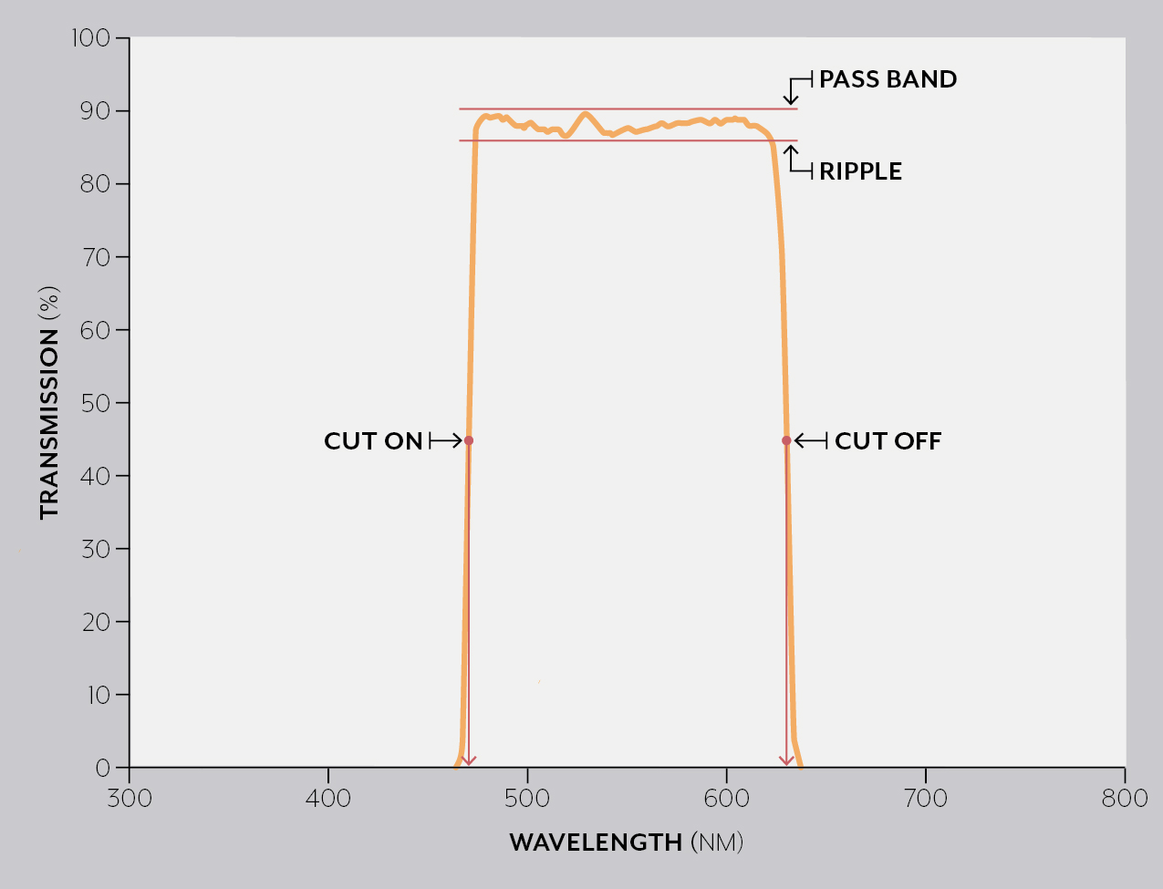
The frequency response of a band-pass filter describes how the filter behaves with different frequencies within its passband. It is a graphical representation of the filter’s response to various input frequencies and provides important information about its performance characteristics.
The frequency response of a band-pass filter is typically represented by a plot of the filter’s gain (amplification factor) against frequency. This plot is known as the frequency response curve. It shows how the filter amplifies or attenuates signals at different frequencies within the passband.
In a well-designed band-pass filter, the gain within the passband is relatively constant and stable, indicating that the filter amplifies signals within that range with minimal distortion. The filter’s gain will typically reach a peak at the center frequency of the passband, representing its maximum amplification capability.
The shape of the frequency response curve depends on the design of the band-pass filter. There are various mathematical functions that can describe the frequency response, such as Butterworth, Chebyshev, and Bessel response. Each function has its own characteristics in terms of sharpness of cutoff, roll-off rate, and passband ripple.
The bandwidth of a band-pass filter is an important parameter that describes the range of frequencies within the passband. It is determined by the difference between the upper and lower cutoff frequencies. A wider bandwidth indicates a broader range of frequencies that the filter can effectively amplify, while a narrower bandwidth allows for more precise filtering of a specific frequency range.
The roll-off rate of a band-pass filter refers to how quickly the gain decreases outside the passband. A steeper roll-off indicates a more rapid attenuation of frequencies outside the passband, resulting in better signal isolation.
The frequency response of a band-pass filter is influenced by various factors, such as the type of filter circuit, the values of the components used, and the design specifications. It is important to consider these factors during the design process to ensure that the filter meets the desired performance requirements for the application.
In practical applications, it is essential to evaluate the frequency response characteristics of a band-pass filter to ensure that it effectively filters the desired frequencies while attenuating unwanted signals. This evaluation can be performed through simulation or physical testing of the filter.
In summary, the frequency response of a band-pass filter describes its behavior with different frequencies within its passband. The frequency response curve shows the gain of the filter at various frequencies, providing information about its amplification and attenuation characteristics. Factors such as bandwidth and roll-off rate greatly influence the performance of the filter. Understanding the frequency response of a band-pass filter is crucial for selecting the appropriate filter for a specific application.
Types of Band-Pass Filters
Band-pass filters come in various types, each with its own characteristics and applications. These types differ in terms of their circuit configurations and the components used to create the frequency-selective response. Understanding the different types of band-pass filters can help in selecting the most suitable one for a specific application.
1. Passive RC Band-Pass Filter: This type of band-pass filter consists of resistors and capacitors arranged in series or parallel configurations. It is a simple and cost-effective filter design that provides moderate performance. Passive RC band-pass filters are commonly used in applications such as audio systems, signal processing, and telecommunications.
2. Passive LC Band-Pass Filter: The passive LC band-pass filter utilizes inductors and capacitors arranged in parallel or series configurations. It offers better performance compared to the passive RC filter and is often used in radio communications, wireless systems, and RF circuits. The LC band-pass filter provides a sharper roll-off and narrower bandwidth.
3. Active Band-Pass Filter: Active band-pass filters incorporate active components, such as operational amplifiers (Op-Amps), in addition to resistors and capacitors. The inclusion of Op-Amps allows for gain control and can amplify weak signals. Active band-pass filters are widely used in audio applications, equalizers, and instrumentation.
4. Digital Band-Pass Filter: Digital band-pass filters are implemented using digital signal processing techniques. They process digital signals in the frequency domain, typically using algorithms such as Fast Fourier Transform (FFT) or Infinite Impulse Response (IIR) filters. Digital band-pass filters are employed in various digital audio processing systems, wireless communication systems, and radar applications.
5. SAW Band-Pass Filter: Surface Acoustic Wave (SAW) band-pass filters use acoustic waves propagated on a piezoelectric substrate. These filters offer high selectivity and narrow bandwidths, making them suitable for applications such as cellular communication, satellite communication, and radar systems.
6. Tunable Band-Pass Filter: A tunable band-pass filter allows for adjusting the center frequency of the passband. This can be achieved by using variable capacitors or inductors, or by employing tunable components such as varactors or voltage-controlled oscillators (VCOs). Tunable band-pass filters find application in frequency synthesizers, wireless communication systems, and spectrum analyzers.
Each type of band-pass filter has its own advantages and limitations, and the choice depends on the specific requirements of the application. Factors to consider include frequency range, passband characteristics, selectivity, cost, and the complexity of the filter design.
In summary, band-pass filters can be classified into various types, such as passive RC filters, passive LC filters, active filters, digital filters, SAW filters, and tunable filters. Each type has its own unique characteristics and applications. Understanding the different types of band-pass filters allows for the appropriate selection of the filter that best suits the desired performance and application requirements.
Active vs. Passive Band-Pass Filters
Band-pass filters can be categorized into two main types: active and passive. The distinction between these types lies in the presence or absence of active components, such as operational amplifiers (Op-Amps), in the filter circuit. Understanding the differences between active and passive band-pass filters can help in selecting the most suitable filter for a specific application.
Passive Band-Pass Filters: Passive band-pass filters are constructed solely using passive components, such as resistors, capacitors, and inductors. They do not require an external power source and rely on the inherent properties of these components to create the frequency-selective response. Passive band-pass filters are relatively simple in design, cost-effective, and have lower power consumption compared to active filters. They find wide application in audio systems, telecommunications, and signal processing. However, passive filters have limited gain and cannot compensate for signal loss, leading to degraded performance for weak input signals.
Active Band-Pass Filters: Active band-pass filters incorporate active components, typically Op-Amps, in addition to passive components. The Op-Amps provide gain and buffering capabilities, allowing for signal amplification and compensating for signal loss. Active band-pass filters are capable of providing higher gain and better signal integrity, making them suitable for applications where weak signals need amplification or impedance matching is required. They offer greater flexibility in filter design and precise control over the passband characteristics, such as gain and frequency response. However, active filters are more complex in design, require an external power source, and are generally more expensive than passive filters.
The choice between active and passive band-pass filters depends on several factors, including the desired gain, input signal strength, power consumption limitations, and application requirements. Passive filters are preferred for simple applications where signal amplification is not required, or when cost and power consumption are critical considerations. Active filters are utilized when high gain, impedance matching, or precise control over the passband characteristics is necessary.
It’s important to note that both active and passive band-pass filters have their own advantages and limitations. The selection of the appropriate filter type depends on the specific requirements of the application, such as the desired signal quality, power constraints, complexity of the circuit, and budget considerations.
In summary, active and passive band-pass filters differ in the presence or absence of active components in the filter circuit. Passive filters are simple, cost-effective, and suitable for applications where signal amplification is not needed. Active filters, on the other hand, offer higher gain, precise control over passband characteristics, and better signal integrity. The choice between active and passive filters depends on the specific application requirements and trade-offs regarding complexity, cost, power consumption, and desired signal quality.
Applications of Band-Pass Filters
Band-pass filters have a wide range of applications across various industries and fields. Their ability to selectively pass a specific range of frequencies while attenuating others makes them invaluable in many different scenarios. Here are some notable applications of band-pass filters:
1. Audio Systems: Band-pass filters are commonly used in audio systems, such as speakers and amplifiers. They help in isolating specific frequency bands, allowing for clearer and more accurate sound reproduction. Band-pass filters are also used in equalizers to adjust the tone and balance of audio signals.
2. Wireless Communications: Band-pass filters play a crucial role in wireless communication systems, including cellular networks, Wi-Fi routers, and Bluetooth devices. They help in filtering out unwanted interference and noise, allowing for reliable and efficient transmission of signals within specific frequency ranges.
3. Radio and Television Broadcasting: Band-pass filters are employed in radio and television broadcasting to limit the frequency range of signals, ensuring that only the desired channels are transmitted and received. This helps in preventing interference between different channels and improves overall signal quality.
4. Medical Instrumentation: Band-pass filters are used in medical instrumentation to isolate specific biological signals within a certain frequency range. For example, in electrocardiography (ECG), band-pass filters are used to isolate the electrical signals generated by the heart, allowing for accurate monitoring and diagnosis.
5. Image Processing: Band-pass filters are utilized in image processing applications to enhance specific frequency components within images. They help in removing noise and emphasizing important details for tasks such as image recognition, edge detection, and image enhancement.
6. Radar Systems: Band-pass filters are integral to radar systems, isolating and amplifying specific frequency components within radar signals. This helps in accurately detecting and tracking objects at specific ranges, improving radar performance and target identification.
7. Scientific Research: Band-pass filters find extensive use in scientific research, particularly in fields like physics and astronomy. They are employed in experiments involving signal analysis, data acquisition, and noise reduction. Band-pass filters help researchers isolate specific frequencies of interest, enabling accurate measurements and analysis.
These are just a few examples of the numerous applications of band-pass filters. Their versatility and effectiveness in isolating specific frequency components make them indispensable in a wide range of industries, contributing to improved signal quality, better communication, accurate measurements, and enhanced system performance.
In summary, band-pass filters find application in audio systems, wireless communications, broadcasting, medical instrumentation, image processing, radar systems, and scientific research. They help in isolating specific frequency bands, improving signal quality, reducing noise, and enhancing system performance in various fields and industries.
Design Considerations for Band-Pass Filters
Designing an effective band-pass filter requires careful consideration of several factors to ensure that it meets the desired specifications and performance requirements. The following are important design considerations for band-pass filters:
1. Passband Range: Determine the desired range of frequencies that the band-pass filter should allow to pass through. This will define the lower and upper cutoff frequencies of the passband. Consider the specific application requirements and the frequency range of the signals of interest.
2. Filter Order: The filter order indicates the steepness of the roll-off outside the passband. Higher-order filters attenuate frequencies outside the passband more rapidly but may introduce phase distortions. Choose an appropriate filter order to balance the desired roll-off characteristics with phase accuracy.
3. Bandwidth: The bandwidth of the filter determines the range of frequencies within the passband. Consider the required bandwidth based on the application’s needs. A narrower bandwidth provides better frequency selectivity but may attenuate desired signals close to the passband edges.
4. Gain: Decide whether the band-pass filter requires gain amplification or not. In some applications, such as audio systems or weak signal processing, a gain stage may be necessary to compensate for signal loss or achieve the desired signal strength.
5. Filter Response: Choose the appropriate type of frequency response for the application. Common responses include Butterworth, Chebyshev, and Bessel. Each has its own trade-offs in terms of steepness of roll-off, passband ripple, and phase distortion. Select the response that best meets the requirements of the application.
6. Component Selection: Carefully select the appropriate passive and active components for the band-pass filter circuit. Consider factors such as component tolerances, temperature stability, and power ratings. The choice of components affects the performance, cost, and size of the filter.
7. Noise Considerations: Evaluate the expected noise levels in the application and design the filter to minimize the impact of noise. Use low-noise components where necessary and consider the filter’s noise figure and signal-to-noise ratio requirements.
8. Impedance Matching: Ensure proper impedance matching between the input and output of the filter to prevent signal reflections and optimize power transfer. This is particularly important when connecting the filter to other components or systems.
9. Filter Stability: Consider stability issues that may arise in active band-pass filters due to feedback loops. Use compensation techniques, such as frequency compensation or feedback stabilization, to maintain stability and prevent oscillations.
10. Testing and Validation: Verify the performance of the designed band-pass filter through simulation and experimental testing. Measure its frequency response, gain, roll-off characteristics, and any other relevant parameters to ensure it meets the specified requirements.
By considering these design considerations, engineers can design band-pass filters that effectively isolate and amplify the desired frequency range while attenuating unwanted signals. A well-designed band-pass filter enhances system performance, improves signal quality, and enables the successful implementation of various applications.
In summary, designing a band-pass filter involves determining the passband range, selecting the filter order and bandwidth, considering gain requirements, choosing the appropriate filter response, selecting suitable components, addressing noise concerns, ensuring impedance matching, ensuring filter stability, and validating the designed filter through testing. Considering these design considerations is essential for achieving the desired performance and functionality of the band-pass filter.