
What Is A Resistor?
A resistor is a passive two-terminal electronic component that is used to control the flow of electric current in a circuit. It is one of the fundamental building blocks of electronic circuits and is widely used in various applications. Resistors are designed to have a specific electrical resistance, which is measured in ohms (Ω). The resistance value determines how much the resistor restricts the flow of current.
Resistors are typically made of materials with high resistance, such as carbon, metal alloys, or ceramic. They come in various shapes and sizes, ranging from small chip resistors to larger cylindrical resistors. The physical size of a resistor is often an indicator of its power rating capability. The larger the size, the higher the power rating, indicating that it can handle more electrical energy without overheating.
When a voltage is applied across a resistor, a potential difference is created, causing a flow of current through the resistor. According to Ohm’s Law, the current passing through a resistor is directly proportional to the voltage across it and inversely proportional to its resistance. This relationship can be expressed mathematically as I = V/R, where I is the current in amperes, V is the voltage in volts, and R is the resistance in ohms.
Resistors have a variety of uses in electronics. They can be used to limit current, divide voltage, maintain signal integrity, compensate for temperature variations, and act as pull-up or pull-down resistors. Additionally, resistors are commonly used in electronic systems such as audio amplifiers, power supplies, digital circuits, and sensors.
How Does A Resistor Work?
To understand how a resistor works, it is important to grasp the concept of electrical resistance. Resistance is the property of a material that opposes the flow of electric current. In a resistor, this property is deliberately incorporated to regulate the current flowing through a circuit.
Resistors are made using materials with high resistance, such as carbon or metal alloys, which impede the flow of electrons. When a voltage is applied across a resistor, it creates an electric field that exerts a force on the electrons. As the electrons move through the resistor, they collide with the atoms in the material, causing a loss of energy in the form of heat.
This energy loss results in a reduction of the current flow. The higher the resistance value of the resistor, the greater the opposition to the flow of electrons and the lower the current that passes through. Conversely, a lower resistance value allows for a higher current flow.
The resistance of a resistor is determined by its physical characteristics, such as length, cross-sectional area, and the nature of the material used. Longer resistors offer more resistance, as the electrons have to travel a greater distance, while wider resistors have lower resistance due to more paths available for electrons to travel through.
Resistors can be connected in series or parallel in a circuit to achieve specific resistance values. In series connection, the resistances add up, resulting in a higher overall resistance. In parallel connection, the inverse of the sum of the reciprocals of the resistances gives the overall resistance, which is lower than any of the individual resistances.
By varying the resistance in a circuit, resistors enable control over the amount of current flowing through different parts of the circuit. This control is crucial for ensuring that components operate within their specified voltage and current ranges, preventing damage or malfunction.
Importance of Resistor in Electronics
Resistors play a crucial role in electronic circuits and systems. Their importance stems from their ability to control the flow of current and provide stability, safety, and functionality to various electronic devices. Let’s explore some key reasons why resistors are essential in electronics.
One of the primary functions of resistors is to limit current. In many electronic components, it is necessary to restrict the amount of current flowing through them to prevent overheating and damage. By placing a resistor in series with these components, the resistor acts as a current limiter, ensuring that the current remains within a safe range.
Resistors also serve as voltage dividers. In electronic circuits, there are instances where the voltage needs to be reduced or divided before reaching certain components. By using resistors in a specific configuration, known as a voltage divider circuit, the voltage can be distributed proportionally across the resistors, allowing precise control of the voltage levels.
Another vital role of resistors is in maintaining signal integrity. In high-frequency applications, signals can be affected by reflections, noise, and interference. By incorporating a resistor in the circuit, it can help match the impedance between different components, reducing signal reflections and ensuring that the intended signal is transmitted accurately.
Resistors also offer temperature compensation. Some electronic components, such as transistors, exhibit variations in performance with changes in temperature. By including a resistor in a temperature compensation network, it can help offset these variations and maintain stable performance across a wide range of temperatures.
Pull-up and pull-down resistors are commonly used in digital circuits. They ensure that input signals have valid logic levels by either providing a high voltage (pull-up) or a low voltage (pull-down) when the input is not actively driven. These resistors are essential in preventing floating inputs and ensuring reliable logic levels.
Resistors come in various types, each with its own specific characteristics and uses. Some common types include carbon film resistors, metal film resistors, and wire wound resistors. The different types allow for precise control of resistance values and cater to various applications and environments.
Overall, resistors are indispensable components in electronics, providing control, stability, and functionality to a wide range of electronic devices and systems. Their ability to limit current, divide voltage, maintain signal integrity, compensate for temperature variations, and act as pull-up or pull-down resistors makes them integral to the world of electronics.
Controlling Current with Resistor
One of the most important functions of a resistor in an electronic circuit is to control the flow of current. By strategically placing resistors within a circuit, the current can be managed to ensure that components operate within their safe operating limits. Let’s explore how resistors are used to control current in electronic systems.
Resistors act as current limiters by restricting the flow of electricity. When a resistor is connected in series with a component, it creates a higher resistance path for the current to flow through. This higher resistance effectively reduces the amount of current that passes through the component, preventing it from drawing excessive current that could cause overheating or damage.
For example, in LED circuits, a resistor is often connected in series with the LED. LEDs have a specific forward voltage requirement, and exceeding this voltage can damage the LED. By using an appropriate resistor, the current flowing through the LED can be limited to ensure it operates within its safe range.
Another way resistors control current is through feedback circuits. In applications such as amplifiers and regulators, feedback loops are used to stabilize and control the output current. Resistors are key components in these feedback networks, helping to set the gain and maintain stability by ensuring the output current is regulated and within desired parameters.
Additionally, resistors are essential in adjusting the bias current in circuits containing active devices like transistors. Biasing refers to the process of providing a suitable current or voltage to establish the proper operating conditions for these devices. By incorporating resistors in biasing networks, the current levels can be precisely controlled, enabling optimal performance of the active components.
Furthermore, resistors are commonly used in current sensing applications. By placing a resistor in series with a load, the voltage drop across the resistor can be measured and used to determine the current flowing through the load. This technique is widely employed in power management systems, battery charging circuits, and motor control applications.
By carefully selecting the resistance value and positioning resistors within a circuit, designers can exert precise control over the current flowing through various components. This control is critical for preventing damage, optimizing performance, and ensuring the longevity of electronic systems.
Voltage Division with Resistor
Resistors play a crucial role in voltage division, a fundamental technique used in electronic circuits to distribute and control voltage levels. By using resistors in specific configurations, it is possible to divide a voltage into different proportions, allowing for precise control and modulation of voltage levels. Let’s delve into how resistors enable voltage division in electronic systems.
When resistors are connected in series, the total resistance is equal to the sum of the individual resistances. According to Ohm’s Law (V = I * R), the voltage drop across each resistor in a series circuit is proportional to its resistance value. As a result, the voltage across each resistor in the series is divided according to their respective resistance values.
For example, by connecting two resistors in series with different resistance values, the voltage across each resistor can be controlled. The ratio of the voltage drop across each resistor is determined by the ratio of their resistance values. This voltage division technique allows for precise modulation of voltage levels and enables effective control over various components in a circuit.
Voltage dividers are commonly used in electronic systems to set reference voltages, generate bias voltages, or modulate voltage levels for specific applications. By carefully selecting the resistance values of the resistors in the voltage divider circuit, specific voltage ratios can be achieved.
This technique finds applications in many areas, such as analog signal conditioning, analog-to-digital converters, voltage references, and operational amplifier circuits. Voltage dividers are particularly useful when it is necessary to scale down a high voltage to a level suitable for measurement or for driving components that operate at lower voltage levels.
It is important to note that voltage division is affected by the loading effect of connected components. If the load placed across the divider circuit draws significant current, it can alter the voltage division ratio and impact the accuracy of the voltage output. Therefore, when designing voltage dividers, it is critical to consider the input and output impedance requirements to ensure optimal performance.
Resistors enable precise control and modulation of voltage levels through voltage division techniques. By carefully designing the resistance values and configurations, electronic engineers can create voltage dividers to meet specific voltage requirements in various applications. This essential function of resistors is widely used in numerous electronic systems, providing stability, control, and versatility.
Maintaining Signal Integrity with Resistor
Signal integrity is critical in electronic circuits, especially those dealing with high-frequency signals. Maintaining the integrity of a signal ensures its accurate transmission and reception without distortion or degradation. Resistors play a significant role in maintaining signal integrity by matching impedance, reducing reflections, and minimizing noise in electronic systems.
Impedance matching is an essential aspect of signal integrity. When a signal passes from one component to another, it encounters impedance mismatches, which can result in signal reflections and signal degradation. By incorporating resistors in impedance matching networks, it is possible to match the impedance of the source, transmission line, and load, minimizing signal reflections and optimizing signal transfer.
In high-frequency applications, transmission lines can introduce undesirable reflections that distort the signal. By terminating the transmission line with resistors, known as termination resistors, the reflections can be minimized. Termination resistors match the characteristic impedance of the transmission line, facilitating the smooth transmission of signals and reducing signal distortion.
Resistors also serve as components in noise reduction circuits. Noise can degrade the quality of a signal, introducing unwanted disturbances and reducing the signal-to-noise ratio. By including resistors in noise filtering networks, they can act as passive noise attenuators, reducing unwanted noise without adversely affecting the desired signal.
In addition, resistive elements can be used to provide appropriate biasing for sensitive components, such as transistors or amplifiers. Properly biased components exhibit improved linearity and reduced distortion, contributing to maintaining signal integrity. By incorporating resistors in biasing networks, it is possible to stabilize and optimize the performance of these components in signal processing circuits.
Signal integrity can also be affected by unwanted capacitive or inductive effects. By placing resistors in strategic locations, they can mitigate these effects by providing a resistive path and reducing the impact of parasitic capacitance or inductance. This helps maintain the integrity of the signal by minimizing the distortion caused by these unwanted effects.
Overall, resistors play a vital role in maintaining the integrity of signals in electronic systems. Their ability to match impedance, reduce reflections, filter noise, provide appropriate biasing, and mitigate parasitic effects ensures the accurate and reliable transmission of signals. As a result, resistors are essential components in various applications, including telecommunications, audio systems, data transmission, and high-speed digital circuits.
Temperature Compensation with Resistor
Temperature changes can have a significant impact on the performance of electronic components, leading to variations in their characteristics and affecting overall system reliability. To counteract these effects, resistors are often utilized for temperature compensation in electronic circuits. By incorporating specific resistor configurations, it is possible to minimize the impact of temperature variations and maintain optimal performance.
One common use of resistors for temperature compensation is in circuit biasing. Many active electronic components, such as transistors, exhibit variations in their properties with changes in temperature. By incorporating temperature-sensitive resistors, known as thermistors, in the biasing network, the changes in resistance due to temperature are utilized to offset the variations in the active components. This compensation technique ensures that the biasing remains stable over a wide temperature range, allowing for consistent and reliable operation.
In precision applications, where accurate voltage or current references are required, temperature compensation is crucial. Voltage reference circuits often utilize resistors with specific temperature coefficients, such as a positive temperature coefficient (PTC) or negative temperature coefficient (NTC). These resistors are chosen to balance out the temperature-dependent variations in other components, providing a stable reference voltage even with changes in temperature.
Temperature compensation is also used in sensor circuits to maintain accuracy. Sensors that rely on resistance changes, such as thermocouples or resistive temperature detectors (RTDs), can be prone to drift due to temperature fluctuations. By employing compensating resistors that exhibit opposite temperature characteristics, the combined effects of the sensor and the resistor compensate for each other, resulting in an accurate and stable measurement, regardless of temperature variations.
Furthermore, resistors can be incorporated in feedback networks to provide temperature stability for amplifiers and oscillators. Temperature compensation resistors are chosen to counteract any variations encountered by electronic components due to changes in temperature. This helps maintain consistent gain, frequency stability, and performance over a wide range of operating conditions.
In digital circuitry, temperature compensation resistors are used to maintain the timing accuracy of clock signals. Temperature fluctuations can result in variations in signal propagation through different components, leading to timing errors. By incorporating temperature compensation resistors, the timing inaccuracies caused by temperature changes can be minimized, ensuring reliable and synchronized operation of digital circuits.
By carefully selecting resistors with appropriate temperature characteristics and incorporating them into electronic circuits, temperature compensation can be achieved. These resistors help counteract the effects of temperature variations, ensuring stability, accuracy, and reliability in various applications, from precision measurement and sensing systems to temperature-sensitive amplifiers and oscillators.
Pull-Up and Pull-Down Resistors
Pull-up and pull-down resistors are commonly used in digital circuits to ensure proper logic levels and prevent undefined states in input signals. These resistors play a crucial role in providing a stable voltage reference when an input is not actively driven. Let’s explore how pull-up and pull-down resistors work and their significance in electronic systems.
When a digital signal is not actively driven to either logic high or logic low state, it can float, resulting in an undefined voltage level. This can lead to unreliable circuit behavior and erroneous readings. Pull-up and pull-down resistors are used to prevent this floating by providing a default logic level to the input signal.
Pull-up resistors connect the input signal to the positive supply voltage, typically logic high (e.g., +5V), when the signal is not actively driven. These resistors ensure that the input is pulled to a known high voltage level, preventing it from floating. When the signal is actively driven low, the pull-up resistor has a relatively high resistance compared to the driving source, allowing the signal to override the resistor and pull the input voltage low.
Pull-down resistors, on the other hand, connect the input signal to the ground or logic low voltage (e.g., 0V). They ensure that the input is pulled to a known low voltage level when it is not actively driven. Similar to pull-up resistors, when the signal is actively driven high, the pull-down resistor has a relatively high resistance compared to the driving source, allowing the signal to override the resistor and pull the input voltage high.
The choice between using pull-up or pull-down resistors depends on the specific application and the desired logic convention. In some cases, pull-up resistors are preferred, while in others, pull-down resistors may be more appropriate. It is important to consider the logic level requirements of the circuit and the behavior of the input devices when deciding between pull-up and pull-down configurations.
Pull-up and pull-down resistors are particularly critical in digital circuits that interact with external devices, such as buttons, switches, or open-collector/drain outputs. When these external devices are not actively driving the input signal, the pull-up or pull-down resistor ensures that the input remains in a defined state, allowing the circuit to interpret the logic level correctly.
It is worth noting that the value of the pull-up or pull-down resistor affects the speed at which the signal changes its state. Lower resistor values offer faster transitions but can consume more power. Higher resistor values offer slower transitions but consume less power. The choice of resistor value should take into account the specific requirements of the circuit.
Pull-up and pull-down resistors are fundamental components in digital circuit design. They provide stability, prevent floating inputs, and ensure proper logic levels in a wide range of applications. By employing these resistors strategically, designers can create robust and reliable digital circuits that are less susceptible to noise, glitches, and unpredictable behavior.
Resistor Types and Their Uses
Resistors are available in various types, each designed with specific characteristics to suit different applications. Understanding the different types of resistors and their uses is essential for selecting the right component for a particular circuit. Let’s explore some common resistor types and their applications:
Carbon Film Resistors: Carbon film resistors are widely used due to their affordability and reliability. They are made by depositing a thin layer of carbon on a ceramic rod or substrate. These resistors are suitable for general-purpose applications in low to moderate power circuits, such as consumer electronics, audio equipment, and power supplies.
Metal Film Resistors: Metal film resistors are known for their stability, low noise, and excellent temperature coefficient characteristics. They are made by depositing a thin metal film, typically nickel-chrome or tin-oxide, onto a ceramic substrate. Metal film resistors are commonly used in precision circuits, audio amplifiers, signal processing, and instrumentation applications.
Wirewound Resistors: Wirewound resistors are constructed by winding a resistance wire, typically nichrome or constantan, around a ceramic or fiberglass core. They offer high power handling capabilities and excellent stability. Wirewound resistors are commonly used in power electronics, motor control circuits, load resistors, and high-frequency applications.
Surface Mount Resistors (SMD): Surface mount resistors are compact and designed for easy mounting on the surface of PCBs. They are available in various form factors, including chip resistors, resistor networks, and array packages. SMD resistors are widely used in modern electronics, such as smartphones, tablets, computers, and automotive electronics.
Thick Film Resistors: Thick film resistors are created by depositing a layer of resistive paste onto a ceramic substrate and then firing it to form the resistive element. They offer good temperature stability, high power handling, and low cost. Thick film resistors find applications in automotive electronics, industrial controls, telecommunication devices, and power modules.
Fusible Resistors: Fusible resistors are designed to act as fuses in case of excessive current flow. They have a higher power rating compared to standard resistors and are constructed with a specific fuse wire to provide overcurrent protection. Fusible resistors are commonly used in circuits that require short-circuit protection and in applications where safety is crucial.
These are just a few examples of resistor types and their uses. Other resistor types include carbon composition resistors, foil resistors, network resistors, and more. When selecting a resistor, it is essential to consider factors such as power rating, tolerance, temperature coefficient, and the specific requirements of the application to ensure optimal performance and reliability.
Resistors are critical components in electronic circuits, providing precise control over current and voltage levels. By understanding the characteristics and appropriate applications of different resistor types, engineers and designers can create robust and efficient electronic systems for a wide range of applications.
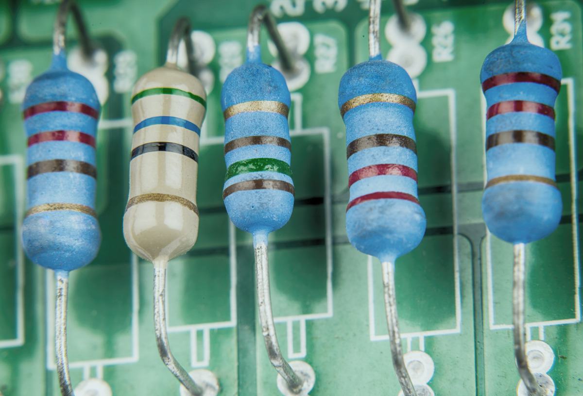
Resistor Color Code
The resistor color code is a standardized system used to indicate the resistance value of resistors through a series of colored bands. This system provides a quick and visual way to identify the resistance of a resistor component. Each color represents a specific numerical value, allowing engineers, technicians, and hobbyists to easily determine the resistance without relying on external measurement devices. Understanding how to decipher the resistor color code is essential when working with electronic circuits.
In the resistor color code system, typically four or five color bands are used to represent the resistance value, tolerance, and sometimes the temperature coefficient. The first two bands indicate the significant digits of the resistance value, while the third band represents the multiplier or the number of zeros to be appended. The fourth band indicates the tolerance, providing the allowable variation from the specified resistance value.
The color code for the numbers 0 to 9 is as follows:
- Black: 0
- Brown: 1
- Red: 2
- Orange: 3
- Yellow: 4
- Green: 5
- Blue: 6
- Violet: 7
- Gray: 8
- White: 9
The multiplier band uses a set of color codes to denote the number of zeros to be added to the significant digit. For example:
- Black: 1
- Brown: 10
- Red: 100
- Orange: 1,000
- Yellow: 10,000
- Green: 100,000
- Blue: 1,000,000
- Violet: 10,000,000
- Gray: 100,000,000
- White: 1,000,000,000
The tolerance band indicates the allowable variation from the specified resistance value and uses the following color codes:
- Gold: 5%
- Silver: 10%
- Brown: 1%
- Red: 2%
- Green: 0.5%
- Blue: 0.25%
- Violet: 0.1%
- Gray: 0.05%
By reading and interpreting the colors of the bands on a resistor, one can determine the resistance value and tolerance. It is important to note that the color code system varies slightly depending on the resistor type and manufacturer, so it is crucial to consult the datasheet or manufacturer specifications for accurate information.
The resistor color code system is a powerful tool that allows for quick identification of resistance values without the need for specialized equipment. By understanding and applying the resistor color code, electronic enthusiasts and professionals can ensure accurate and efficient circuit assembly and troubleshooting.
Common Resistor Applications in Electronics
Resistors are fundamental components used in a wide range of electronic applications. They play vital roles in controlling current, dividing voltage, maintaining signal integrity, and compensating for temperature variations. Let’s explore some common applications where resistors are extensively used:
Audio Circuits: Resistors are crucial in audio circuits, including audio amplifiers, equalizers, and filters. They help set the gain and impedance levels, ensuring proper signal amplification and shaping. Additionally, resistors are used in voltage dividers to control volume levels or create attenuation networks.
Power Supplies: Resistor networks are commonly used in power supply circuits to provide accurate voltage regulation and current limiting. They help stabilize the output voltage and control the maximum current that can be drawn by the load. In linear power supplies, resistors are used in voltage divider circuits for feedback and to set reference voltage levels.
Digital Circuits: Pull-up and pull-down resistors are extensively utilized in digital circuits to ensure proper logic levels when inputs are not actively driven. They prevent floating inputs, minimize noise, and establish defined voltage levels, enhancing the performance and reliability of digital systems.
Temperature Sensors: Resistive temperature detectors (RTDs) and thermistors are common temperature sensing elements in electronic systems. The resistance of these devices changes with temperature, allowing accurate temperature measurement. They find applications in thermostats, environmental monitoring, industrial control systems, and temperature compensation circuits.
Filters: Resistors are integral components in various filter circuits, such as low-pass, high-pass, band-pass, and notch filters. They help determine the cutoff frequency and shape the frequency response of the filter. These filters are widely used in audio processing, telecommunications, and signal conditioning circuits.
Signal Processing: In signal processing circuits, resistors are used in voltage dividers, summing amplifiers, and biasing networks. They help shape and condition signals in applications like instrumentation amplifiers, analog-to-digital converters, and active filters. Resistors also play a role in impedance matching circuits for optimal signal transfer between different devices.
Feedback Networks: In amplifiers and oscillators, resistors are used in feedback networks to stabilize and control the gain, frequency response, and stability of the circuit. They facilitate feedback loops, allowing precise control over the output characteristics and maintaining optimal performance across a range of operating conditions.
Light Emitting Diode (LED) Circuits: Resistors are essential components in LED circuits to limit the current flow and prevent damage to the LED. They are placed in series with the LED to ensure that it operates within its safe current range and defined forward voltage requirements.
Industrial Controls: Resistors find applications in various industrial control systems, such as motor control, power monitoring, and process control. They are used in current sensing circuits, load banks, voltage dividers, and feedback networks to ensure the accuracy, stability, and reliability of the control systems.
These are just a few examples of the numerous applications of resistors in electronics. Their versatility and ability to control current, divide voltage, maintain signal integrity, and compensate for temperature variations make them integral components in a wide range of electronic circuits and systems. Whether in consumer electronics, telecommunications, automotive, or industrial control, resistors are essential for reliable and efficient operation of electronic devices.