
Types of PCB Connectors
Types of PCB Connectors
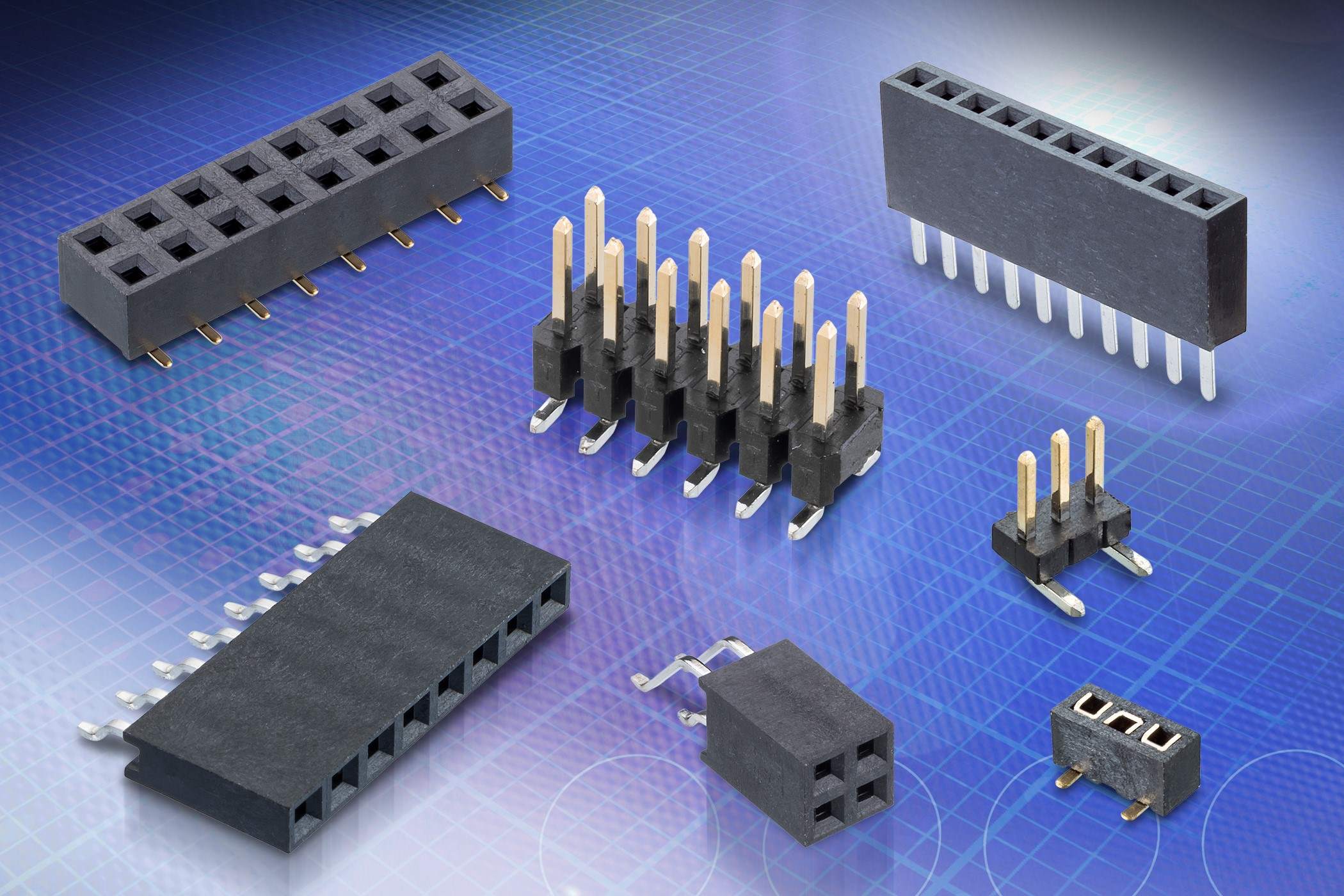
PCB connectors play a crucial role in electronic devices, facilitating the seamless transmission of signals and power between different components. Understanding the various types of PCB connectors is essential for designing and assembling electronic circuits. Here are some common types of PCB connectors:
1. Pin Header Connectors
Also known as male headers, pin header connectors feature a row of pins that are inserted into a corresponding female connector. These connectors are widely used in circuit boards and are available in single, double, or triple-row configurations.
2. Socket Header Connectors
Socket header connectors, also referred to as female headers, are designed to receive pin header connectors. They provide a reliable and secure connection, making them suitable for various applications, including computer and industrial electronics.
3. Terminal Blocks
Terminal blocks are modular, insulated blocks that secure two or more wires together. They are commonly used in industrial and commercial settings to connect wiring to PCBs, providing a convenient means of connecting and disconnecting wires without soldering.
4. Board-to-Board Connectors
These connectors enable the connection of two PCBs, allowing for data and power transmission between them. Board-to-board connectors come in various configurations, including mezzanine, stacking, and perpendicular styles, catering to different design requirements.
5. Wire-to-Board Connectors
Wire-to-board connectors are utilized to establish a connection between a wire and a PCB. They are commonly found in applications such as automotive electronics, consumer electronics, and industrial equipment, offering a reliable interface for signal and power transfer.
Understanding the distinct characteristics and applications of these PCB connectors is fundamental for selecting the most suitable option for a specific electronic design.
Understanding Connector Terminology
Understanding Connector Terminology
When delving into the realm of PCB connectors, it’s essential to grasp the terminology associated with these vital components. Familiarizing oneself with connector terminology not only aids in effective communication but also facilitates the selection and utilization of the most appropriate connectors for a given application. Here are key terms to understand:
1. Pitch
The pitch refers to the distance between the center of one pin to the center of the adjacent pin in a connector. It plays a crucial role in determining the density and compatibility of connectors, especially in applications where space is limited.
2. Mounting Style
Connector mounting styles encompass various methods of attaching connectors to PCBs or other electronic devices. Common mounting styles include through-hole, surface mount, and press-fit, each offering distinct advantages based on the specific assembly requirements.
3. Termination Type
The termination type indicates how a connector is attached to a wire or PCB. It can include options such as crimp, solder, insulation displacement, and IDC (insulation displacement connection), each suited for different applications and wire types.
4. Gender
Connectors are classified based on gender, with male and female connectors designed to interlock with each other. Understanding the gender of connectors is crucial for ensuring proper mating and reliable connections within a circuit.
5. Keying
Keying features in connectors prevent mismating by ensuring that connectors are oriented correctly during assembly. Keying can be achieved through various methods, including polarizing slots, tabs, and coding pins, enhancing the reliability of connections.
By familiarizing oneself with these fundamental connector terms, engineers, designers, and enthusiasts can navigate the world of PCB connectors with confidence, enabling informed decisions and seamless integration of connectors into electronic designs.
Key Considerations for Choosing PCB Connectors
Key Considerations for Choosing PCB Connectors
When selecting PCB connectors for a specific application, several crucial considerations come into play. These considerations are pivotal in ensuring optimal performance, reliability, and compatibility within electronic designs. Here are key factors to contemplate when choosing PCB connectors:
1. Electrical Requirements
Understanding the electrical specifications of the application is paramount. Factors such as voltage, current, and signal integrity requirements must be carefully evaluated to select connectors capable of handling the anticipated electrical loads without compromising performance or safety.
2. Mechanical Durability
Consider the mechanical stresses and environmental conditions to which the connectors will be exposed. Connectors intended for harsh industrial environments, for instance, require robust construction and resistance to vibration, moisture, and temperature fluctuations to ensure long-term reliability.
3. Space Constraints
Space limitations within electronic assemblies necessitate careful consideration of connector size, pitch, and mounting style. Compact designs may call for low-profile or miniature connectors, while high-density applications require connectors with smaller pitches to maximize board real estate.
4. Environmental Factors
Environmental considerations, such as exposure to chemicals, humidity, and extreme temperatures, dictate the selection of connectors with appropriate material compositions and protective coatings. This ensures the connectors can withstand the intended operating conditions without degradation.
5. Industry Standards and Compliance
Adherence to industry standards and regulatory requirements is crucial. Selecting connectors that comply with relevant standards ensures compatibility, interoperability, and safety, thereby mitigating potential issues associated with non-compliant components.
By carefully evaluating these key considerations, engineers and designers can make informed decisions when choosing PCB connectors, ultimately contributing to the seamless integration and reliable performance of electronic systems.
Common Mistakes to Avoid When Using PCB Connectors
Common Mistakes to Avoid When Using PCB Connectors
While PCB connectors are essential components in electronic designs, certain common mistakes can lead to performance issues, reliability concerns, and assembly challenges. Recognizing and avoiding these pitfalls is crucial for ensuring the optimal functionality and longevity of electronic systems. Here are some common mistakes to steer clear of when using PCB connectors:
1. Improper Connector Selection
Choosing connectors solely based on cost or availability without considering the specific electrical, mechanical, and environmental requirements of the application can lead to compatibility issues, premature failures, and compromised performance.
2. Incorrect Termination Techniques
Using improper termination methods, such as incorrect soldering techniques or crimping procedures, can result in unreliable connections, signal degradation, and susceptibility to mechanical stress, ultimately impacting the overall functionality of the electronic system.
3. Overlooking Environmental Considerations
Failure to account for environmental factors, such as exposure to moisture, dust, or temperature extremes, when selecting connectors can lead to premature corrosion, insulation breakdown, and diminished reliability, especially in outdoor or industrial applications.
4. Disregarding ESD Protection
Neglecting to incorporate electrostatic discharge (ESD) protection features in connectors can render electronic devices vulnerable to ESD events, potentially causing damage to sensitive components and leading to operational malfunctions.
5. Ignoring Connector Mating and Unmating Forces
Failure to consider the mating and unmating forces of connectors can result in difficulties during assembly and maintenance, leading to mechanical stress on the connectors and the PCB, potentially causing damage or misalignment.
By being mindful of these common mistakes and taking proactive measures to address them, designers and engineers can optimize the performance, reliability, and serviceability of electronic systems utilizing PCB connectors.
Tips for Properly Installing and Maintaining PCB Connectors
Tips for Properly Installing and Maintaining PCB Connectors
Proper installation and maintenance practices are essential for ensuring the longevity, reliability, and performance of PCB connectors within electronic systems. By adhering to best practices, engineers and technicians can mitigate potential issues and optimize the functionality of these critical components. Here are valuable tips for the proper installation and maintenance of PCB connectors:
1. Follow Manufacturer Guidelines
Adhere to the manufacturer’s recommended installation procedures and guidelines. This includes employing the specified tools, techniques, and environmental conditions to ensure the connectors are installed correctly and securely.
2. Inspect for Damage
Prior to installation, carefully inspect connectors for any signs of damage, such as bent pins, cracked housings, or contamination. Damaged connectors should be replaced to prevent potential performance issues and reliability concerns.
3. Ensure Proper Alignment
During installation, ensure that the connectors are aligned correctly with the corresponding mating components. Misalignment can lead to mating difficulties, mechanical stress, and potential damage to the connectors and the PCB.
4. Implement Secure Fixation
Utilize appropriate fixation methods, such as soldering, crimping, or fastening, to securely affix the connectors to the PCB. This promotes stable electrical connections and minimizes the risk of intermittent contact or disconnection.
5. Establish Regular Inspection and Maintenance
Implement a routine inspection schedule to assess the condition of connectors and address any signs of wear, contamination, or degradation promptly. Routine maintenance helps prevent unexpected failures and ensures continued reliability.
6. Utilize ESD Protection
When handling connectors, employ electrostatic discharge (ESD) protection measures to safeguard the components from potential damage caused by electrostatic events. This includes using ESD-safe workstations, attire, and handling equipment.
By incorporating these tips into the installation and maintenance practices, individuals responsible for integrating PCB connectors into electronic systems can enhance the reliability, longevity, and overall performance of the interconnected components.