
Understanding the Rear Defroster System
The rear defroster system in a vehicle is an essential component that ensures optimal visibility by removing condensation and frost from the rear window. It consists of several key elements, including the rear defroster connector, the electrical wiring, and the defroster grid on the rear window. The defroster grid is typically made of thin, parallel lines of resistive material that generate heat when an electrical current passes through them. This heat, in turn, helps to eliminate moisture and frost buildup on the window, enhancing the driver's visibility, especially in inclement weather conditions.
The rear defroster connector plays a crucial role in supplying power to the defroster grid. It is typically located on the rear window and serves as the point of connection between the vehicle's electrical system and the defroster grid. When the connector is damaged, it can disrupt the flow of electricity to the grid, rendering the defroster system ineffective.
Understanding the functionality of the rear defroster system is vital for diagnosing and addressing issues related to the connector. A malfunctioning or damaged connector can lead to diminished visibility, posing safety risks for the driver and passengers, particularly during adverse weather conditions.
Moreover, being familiar with the rear defroster system empowers vehicle owners to perform basic maintenance and repairs, such as addressing connector damage, without the need for professional assistance. By gaining insights into the system's components and their interplay, individuals can effectively troubleshoot and resolve issues, thereby ensuring the optimal performance of the rear defroster system.
In essence, comprehending the rear defroster system, including the role of the connector, is fundamental for maintaining a clear and unobstructed view through the rear window, promoting safe driving practices, and addressing connector-related issues effectively.
Assessing the Damage to the Rear Defroster Connector
Before embarking on the repair of a rear defroster connector, it is crucial to conduct a comprehensive assessment of the damage. This involves a systematic evaluation of the connector to determine the nature and extent of the impairment. Common indicators of a damaged rear defroster connector include visible cracks, breaks, or corrosion, which can impede the flow of electrical current to the defroster grid.
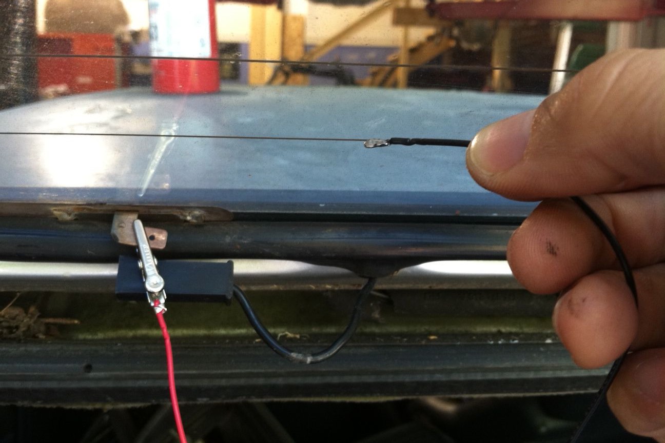
One of the initial steps in assessing the damage is to visually inspect the connector for any signs of physical deterioration. This may involve carefully examining the area surrounding the connector on the rear window, as well as the wiring leading to the connector. Additionally, conducting a voltage test using a multimeter can help ascertain whether there is a disruption in the electrical continuity caused by the damaged connector.
Furthermore, it is essential to consider environmental factors that may have contributed to the damage, such as extreme temperature variations, moisture, or the use of abrasive cleaning agents. Understanding the potential causes of the damage can provide valuable insights into preventive measures to mitigate future issues.
Another aspect of the assessment involves evaluating the impact of the damaged connector on the overall functionality of the rear defroster system. This entails observing the effectiveness of the defroster grid in clearing condensation and frost from the rear window. If the damage to the connector has resulted in the inoperability of the defroster system, prompt remedial action is imperative to ensure uninterrupted visibility while driving.
By thoroughly assessing the damage to the rear defroster connector, individuals can gain a clear understanding of the repair requirements and determine the most suitable approach for restoring the connector’s functionality. This proactive evaluation sets the stage for the subsequent steps involved in repairing or replacing the damaged connector, facilitating a targeted and effective resolution of the issue.
Gathering the Necessary Tools and Materials
Before commencing the repair of a rear defroster connector, it is essential to gather the requisite tools and materials to ensure a smooth and efficient restoration process. The following items are indispensable for effectively addressing the damage to the connector:
- Replacement Connector: Acquire a suitable replacement connector that is compatible with the vehicle’s rear defroster system. Ensure that the connector matches the specifications of the original component to guarantee seamless integration and optimal performance.
- Electrical Tape: High-quality electrical tape is essential for securing and insulating the electrical connections. It provides protection against moisture and ensures the durability and reliability of the repaired connector.
- Multimeter: A multimeter is a vital tool for diagnosing electrical issues and verifying the continuity of the repaired connector. It enables precise voltage and resistance measurements, facilitating the accurate assessment of the connector’s functionality.
- Wire Strippers and Crimping Tool: These tools are indispensable for stripping and crimping the electrical wires, ensuring secure connections between the new connector and the existing wiring. They contribute to the precision and durability of the repair work.
- Cleaning Solution and Cloth: A mild cleaning solution and a soft cloth are essential for preparing the area around the damaged connector. Thoroughly cleaning the surface ensures proper adhesion and electrical conductivity when installing the replacement connector.
- Protective Gloves and Eyewear: Safety is paramount during the repair process. Wearing protective gloves and eyewear safeguards against potential injury and exposure to electrical components and cleaning agents.
Additionally, it is advisable to have a well-lit and adequately ventilated workspace to facilitate the repair process. Adequate lighting enhances visibility and precision, while proper ventilation ensures a comfortable and safe working environment.
By gathering the necessary tools and materials in advance, individuals can streamline the repair process and mitigate potential delays or interruptions. Preparedness and attention to detail in assembling the required components contribute to the efficiency and effectiveness of the rear defroster connector repair, ultimately ensuring the restoration of the defroster system’s optimal functionality.
Removing the Damaged Rear Defroster Connector
Removing a damaged rear defroster connector is a critical step in the repair process, and it involves careful execution to avoid causing further harm to the vehicle’s electrical system and the rear window. The following steps outline the systematic approach to safely and effectively removing the damaged connector:
- Disconnect the Power Source: Prior to initiating any work on the rear defroster system, it is imperative to disconnect the power source to prevent electrical hazards. This typically involves disconnecting the vehicle’s battery to ensure the safety of the repair process.
- Identify the Connector Location: Locate the position of the damaged rear defroster connector on the rear window. Carefully examine the surrounding area to identify any additional components, such as retaining clips or adhesive materials, that may secure the connector in place.
- Detach the Wiring: Gently detach the wiring connected to the damaged connector, ensuring minimal disturbance to the surrounding components. Exercise caution to avoid causing damage to the wiring or the defroster grid on the rear window.
- Remove Retaining Hardware: If the damaged connector is secured with retaining hardware, such as clips or fasteners, carefully remove these components to facilitate the extraction of the connector. Utilize appropriate tools, such as screwdrivers or pliers, to disengage and safely store the retaining hardware for reinstallation.
- Clean the Area: After removing the damaged connector, thoroughly clean the surrounding area on the rear window to eliminate any residue or debris. Use a mild cleaning solution and a soft cloth to ensure a clean and smooth surface for the installation of the replacement connector.
Throughout the removal process, meticulous attention to detail and a gentle touch are essential to prevent unintended damage to the vehicle’s components. Additionally, adhering to safety protocols, such as wearing protective gloves and eyewear, is imperative to safeguard against potential injuries and exposure to electrical elements.
By methodically following these steps, individuals can effectively remove the damaged rear defroster connector, laying the groundwork for the subsequent installation of the replacement component. This systematic approach ensures the integrity of the vehicle’s electrical system and paves the way for a seamless transition to the repair phase, ultimately restoring the functionality of the rear defroster system.
Preparing the Area for the New Connector
Preparing the area for the installation of the new rear defroster connector is a crucial phase in the repair process, as it sets the stage for the seamless integration and optimal functionality of the replacement component. The following steps outline the essential measures to prepare the area effectively:
- Verify Compatibility: Prior to installation, ensure that the new connector is compatible with the vehicle’s rear defroster system. Verify the dimensions, electrical specifications, and mounting features to guarantee a precise fit and seamless integration.
- Clean the Mounting Surface: Thoroughly clean the mounting surface on the rear window using a mild cleaning solution and a soft cloth. Remove any residual adhesive, debris, or contaminants to ensure a smooth and clean surface for affixing the new connector.
- Inspect the Wiring: Carefully inspect the wiring that will connect to the new connector. Verify the integrity of the wiring, ensuring that it is free from damage, fraying, or corrosion. Address any issues with the wiring to ensure reliable electrical connections.
- Positioning and Alignment: Determine the precise positioning and alignment of the new connector on the rear window. Align the mounting points and ensure that the connector is oriented correctly to facilitate the seamless attachment and electrical connectivity.
- Secure Retaining Hardware: If the new connector requires retaining hardware, such as clips or fasteners, ensure that these components are readily accessible and securely positioned for the installation process. Verify the compatibility and integrity of the retaining hardware to guarantee stability and longevity.
Throughout the preparation phase, meticulous attention to detail and precision are paramount to ensure the successful installation of the new rear defroster connector. Additionally, maintaining a clean and organized workspace contributes to a streamlined and efficient repair process.
By diligently executing these preparatory measures, individuals can establish an optimal foundation for integrating the new connector into the rear defroster system. This proactive approach ensures the reliability, functionality, and longevity of the repaired rear defroster connector, ultimately contributing to enhanced visibility and safety while driving.
Installing the New Rear Defroster Connector
Installing a new rear defroster connector is a pivotal phase in the repair process, and it demands meticulous attention to detail and precision to ensure the seamless integration and optimal functionality of the replacement component. The following steps outline the systematic approach to installing the new connector:
- Positioning the Connector: Carefully position the new connector on the designated mounting area of the rear window, aligning it with precision to facilitate secure attachment and optimal electrical connectivity.
- Securing the Connector: If the new connector utilizes retaining hardware, such as clips or fasteners, securely affix these components to ensure the stability and longevity of the installed connector. Verify the integrity of the retaining hardware to guarantee a reliable and durable attachment.
- Connecting the Wiring: Gently connect the wiring from the vehicle’s electrical system to the corresponding terminals on the new connector. Exercise caution to avoid strain or damage to the wiring, ensuring secure and reliable electrical connections.
- Insulating the Connections: Utilize high-quality electrical tape to insulate and secure the electrical connections, safeguarding them against moisture and environmental elements. Ensure thorough insulation to promote the durability and reliability of the installed connector.
- Verifying Electrical Continuity: Utilize a multimeter to verify the electrical continuity of the installed connector, conducting precise voltage and resistance measurements to ensure optimal functionality and performance.
Throughout the installation process, a methodical and meticulous approach is essential to guarantee the integrity and reliability of the new rear defroster connector. Adhering to safety protocols, such as wearing protective gloves and eyewear, is imperative to safeguard against potential injuries and ensure a secure and efficient installation.
By conscientiously following these steps, individuals can effectively install the new rear defroster connector, culminating in the seamless integration of the replacement component into the vehicle’s rear defroster system. This systematic approach ensures the restoration of the system’s optimal functionality, contributing to enhanced visibility and safety while driving in diverse weather conditions.
Testing the Rear Defroster System
Following the installation of a new rear defroster connector, it is imperative to conduct a comprehensive testing process to verify the functionality and effectiveness of the rear defroster system. The testing phase serves as a critical validation of the repair work and ensures that the system operates optimally, providing clear visibility through the rear window. The following steps outline the systematic approach to testing the rear defroster system:
- Power Activation: Reconnect the vehicle’s battery to restore power to the rear defroster system. Ensure that the electrical connections are secure and that all safety protocols, such as protective gloves and eyewear, are in place before activating the system.
- Observation of Defroster Grid: Activate the rear defroster system and observe the defroster grid on the rear window. Verify that the grid heats up uniformly, indicating the proper distribution of electrical current and the functionality of the new connector.
- Visibility Assessment: Assess the effectiveness of the defroster system in clearing condensation and frost from the rear window. Observe the clarity and rapidity of defrosting, ensuring that the system provides unobstructed visibility for safe driving in varied weather conditions.
- Voltage and Continuity Check: Utilize a multimeter to conduct a voltage and continuity check on the rear defroster system. Verify the voltage output and continuity of the electrical connections, ensuring that the system operates within the specified parameters and that the new connector functions reliably.
- Operational Validation: Engage the rear defroster system in diverse weather conditions, including cold and humid environments, to validate its operational efficacy. Confirm that the system consistently maintains a clear and defogged rear window, enhancing driver visibility and safety.
Thorough and methodical testing of the rear defroster system is instrumental in validating the successful repair and installation of the new connector. It provides assurance of the system’s optimal functionality and reliability, ensuring that it effectively addresses condensation and frost buildup on the rear window.
By diligently following these testing procedures, individuals can ascertain the proper operation of the rear defroster system, thereby confirming the efficacy of the repair work and the seamless integration of the new connector. This rigorous validation process ultimately contributes to enhanced visibility and safety while driving, especially in challenging weather conditions.