
Understanding VGA Connectors
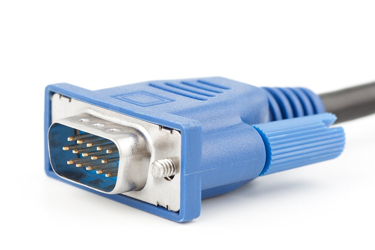
VGA, or Video Graphics Array, connectors are widely used to transmit video signals between a computer or other electronic devices and a display monitor. These connectors are recognizable by their trapezoidal shape and the three rows of pins they contain. VGA connectors have been a standard feature on computers and monitors for many years, and while newer digital interfaces like HDMI and DisplayPort have gained popularity, VGA remains relevant in various applications.
VGA connectors are analog, meaning they transmit information through continuously variable signals, as opposed to the digital signals used by newer interfaces. Despite this, VGA connectors are still commonly found in educational institutions, businesses, and older computer systems. Understanding VGA connectors is essential for anyone working with older equipment or seeking to connect legacy devices to modern displays.
VGA connectors are often used to connect desktop computers, laptops, projectors, and some televisions to monitors or other display devices. The analog nature of VGA signals means that they are subject to interference and degradation over long cable runs, so it's important to understand the limitations of VGA technology when planning a video setup.
The standard VGA connector has 15 pins, with three rows of five pins each. Each pin serves a specific function in transmitting the video signal from the source device to the display. Understanding the purpose of each pin is crucial for troubleshooting connection issues and ensuring the correct transmission of video data.
In addition to their use in video transmission, VGA connectors can also carry separate horizontal and vertical synchronization signals, allowing for the proper synchronization of the display with the video signal. This synchronization is essential for ensuring that the video image is displayed correctly and without distortion.
By understanding the role of VGA connectors in video transmission and their continued relevance in various settings, individuals can effectively utilize and troubleshoot these connectors in a range of applications. Whether connecting a legacy computer to a monitor or integrating older AV equipment into a modern setup, a solid understanding of VGA connectors is invaluable.
Importance of Counting Pins on a VGA Connector
Counting the pins on a VGA connector is crucial for identifying the specific functions and capabilities of the connector. Understanding the pin configuration enables individuals to determine the type of video signal being transmitted, troubleshoot connection issues, and ensure compatibility between devices. Whether working with legacy equipment or diagnosing display problems, the importance of counting pins on a VGA connector cannot be overstated.
One of the key reasons for counting pins on a VGA connector is to identify the type of video signal being transmitted. VGA connectors can carry various types of analog video signals, and the pin configuration provides vital information about the signal format. By counting the pins and referencing the pinout diagram, individuals can determine whether the connector supports standard VGA, SVGA, XGA, or other video formats, allowing them to select the appropriate display device and ensure compatibility.
Furthermore, counting pins on a VGA connector is essential for troubleshooting connection issues. If a video signal is not being properly transmitted or displayed, checking the pin configuration can help identify potential sources of the problem. Loose or damaged pins, incorrect cable connections, or mismatched pin assignments can all lead to video signal issues, and a thorough understanding of the connector’s pinout is invaluable for diagnosing and resolving these issues.
Additionally, the importance of counting pins on a VGA connector extends to ensuring compatibility between devices. Different VGA connectors may have distinct pin configurations, and understanding these differences is essential when connecting devices. By accurately counting the pins and verifying the pinout, individuals can confirm that the connector is compatible with the target display device, preventing potential damage to equipment and ensuring the successful transmission of the video signal.
Whether working with older computer systems, integrating legacy AV equipment, or troubleshooting display problems, the ability to count pins on a VGA connector is a fundamental skill. By recognizing the importance of understanding the pin configuration, individuals can effectively manage video connections, diagnose issues, and maintain compatibility between devices, ultimately optimizing the performance of their video setups.
Identifying the Pins on a VGA Connector
Identifying the pins on a VGA connector is essential for understanding the functions and capabilities of each pin in transmitting the video signal. With a standard VGA connector containing 15 pins arranged in three rows, it is crucial to recognize the specific roles of each pin to ensure proper signal transmission and troubleshoot potential issues. By familiarizing oneself with the pinout diagram and the functions of individual pins, individuals can effectively work with VGA connectors and optimize their video setups.
The 15 pins on a VGA connector are designated with specific numbers and colors, each serving a distinct purpose in transmitting the video signal. Pin 1, for example, is assigned to the red video signal, while pin 2 carries the green video signal, and pin 3 is dedicated to the blue video signal. These color-coded pins are crucial for transmitting the primary video components and are essential for generating the full-color image on the display device.
Beyond the primary video signals, the VGA connector also includes pins for horizontal and vertical synchronization, which are vital for ensuring the proper alignment and refresh of the video image. Pins 13 and 14 are dedicated to horizontal and vertical synchronization, respectively, allowing the display device to synchronize with the incoming video signal and maintain the correct image position and stability.
Identifying the ground pins on a VGA connector is also crucial, as these pins provide a reference voltage level and ensure proper signal integrity. Ground pins, typically labeled as GND, serve to stabilize the video signal and prevent interference, contributing to the overall quality of the displayed image.
By recognizing and understanding the functions of each pin on a VGA connector, individuals can effectively troubleshoot video signal issues, ensure compatibility between devices, and optimize the transmission of analog video signals. Whether connecting a computer to a monitor, integrating legacy AV equipment, or diagnosing display problems, a comprehensive understanding of the pinout and the roles of individual pins is essential for successfully working with VGA connectors.
Tools Needed for Counting Pins on a VGA Connector
Counting the pins on a VGA connector requires specific tools to accurately identify and understand the pin configuration. Whether for troubleshooting connection issues, verifying compatibility between devices, or integrating legacy equipment into modern setups, the following tools are essential for effectively counting pins on a VGA connector:
- Magnifying Glass: A magnifying glass can be invaluable for closely inspecting the tiny pins within the VGA connector. This tool helps individuals to clearly see and count the pins, especially when dealing with connectors in tight or hard-to-reach spaces.
- Pinout Diagram: Having access to a pinout diagram for the specific VGA connector being used is essential. The pinout diagram provides a visual reference for the pin numbers, colors, and functions, allowing individuals to accurately count and identify each pin on the connector.
- Flashlight: In dimly lit environments, a flashlight can aid in illuminating the VGA connector, making it easier to discern the individual pins and their configurations. This tool is particularly useful when working with connectors located in areas with limited visibility.
- Small Mirror: When dealing with connectors positioned in challenging locations, a small mirror can assist in obtaining a clear view of the connector’s pins. By strategically positioning the mirror, individuals can effectively count the pins without having to physically access the connector directly.
- Continuity Tester: A continuity tester, such as a multimeter, can be used to verify the connections and functionality of the pins on the VGA connector. This tool helps individuals confirm that each pin is properly connected and can aid in diagnosing potential issues with the connector.
By utilizing these essential tools, individuals can accurately count and identify the pins on a VGA connector, enabling them to troubleshoot video signal problems, ensure compatibility with display devices, and effectively manage analog video connections. Whether in a professional IT environment or for personal use, having the right tools for counting pins on a VGA connector is crucial for maintaining reliable video transmission and optimizing display setups.
Step-by-Step Guide to Counting Pins on a VGA Connector
Counting the pins on a VGA connector is a fundamental task for understanding the connector’s configuration and ensuring proper signal transmission. By following this step-by-step guide, individuals can accurately count and identify the pins on a VGA connector, enabling them to troubleshoot video signal issues, verify compatibility, and optimize their video setups.
- Obtain a Pinout Diagram: Before beginning, acquire a pinout diagram specific to the VGA connector being used. The pinout diagram provides a visual reference for the pin numbers, colors, and functions, serving as a crucial tool for accurate pin counting.
- Inspect the Connector: Carefully examine the VGA connector, ensuring that it is free from dust, debris, or any obstructions that may hinder the counting process. Clean the connector if necessary to provide a clear view of the pins.
- Position the Connector: If the VGA connector is located in a tight or hard-to-reach space, use a flashlight and a small mirror to illuminate and view the connector from various angles. Ensure that the connector is accessible for counting the pins.
- Use a Magnifying Glass: For connectors with small or closely spaced pins, utilize a magnifying glass to clearly see and count the individual pins. This tool can aid in accurately identifying each pin and its corresponding number and color.
- Count and Verify Each Pin: Begin counting the pins, starting from pin 1 and proceeding through each pin in numerical order. Refer to the pinout diagram to confirm the color and function of each pin, ensuring that the count is accurate and matches the diagram.
- Check for Damage or Misalignment: While counting the pins, inspect each pin for any signs of damage, misalignment, or foreign objects that may affect the connector’s functionality. Ensure that the pins are clean, straight, and properly seated within the connector.
- Verify Pin Functions: Once the pins are counted, verify the functions of each pin based on the pinout diagram. Ensure that the colors and functions align with the expected configuration for the specific VGA connector type.
- Document the Pin Configuration: Record the counted pin configuration, including the pin numbers, colors, and functions, for future reference. This documentation can be valuable for troubleshooting, compatibility verification, and maintaining accurate records of the connector’s pinout.
By following this step-by-step guide, individuals can confidently count the pins on a VGA connector, gaining a comprehensive understanding of the connector’s configuration and functionality. Whether working with legacy equipment, diagnosing video signal issues, or integrating VGA connectors into modern setups, a thorough knowledge of the pinout is essential for optimizing analog video connections.
Common Issues with VGA Connectors
VGA connectors, despite their widespread use and reliability, are susceptible to several common issues that can affect video signal transmission and display quality. Understanding these issues is crucial for effectively troubleshooting and addressing potential problems that may arise when working with VGA connectors.
- Loose or Damaged Pins: One of the most prevalent issues with VGA connectors is the presence of loose or damaged pins. Over time, frequent plugging and unplugging of cables can lead to pin misalignment or damage, resulting in poor or intermittent connectivity and signal transmission.
- Interference and Signal Degradation: VGA connectors, being analog in nature, are susceptible to interference and signal degradation, particularly over long cable runs. This can result in visual artifacts, color distortion, or a loss of image clarity, impacting the overall display quality.
- Compatibility and Resolution Mismatch: Incompatibility between the video signal output from the source device and the capabilities of the display monitor can lead to resolution mismatch and improper image rendering. This issue may manifest as distorted or out-of-sync visuals on the display.
- Pin Configuration Errors: Incorrect pin connections or misalignment during cable installation can lead to pin configuration errors, causing the video signal to be improperly transmitted. Identifying and rectifying these errors is essential for ensuring reliable signal transmission.
- Grounding and Signal Integrity: Poor grounding or signal integrity within the VGA connector can result in image flickering, color inconsistencies, or signal dropouts. Maintaining proper grounding and signal integrity is crucial for preserving the quality of the video signal.
- Connector Wear and Tear: Continuous use and aging can lead to wear and tear of VGA connectors, potentially resulting in diminished contact reliability and signal transmission. Regular inspection and maintenance are essential for addressing connector degradation.
Addressing these common issues with VGA connectors requires a systematic approach to troubleshooting, including careful inspection of the connector, cable, and connected devices. By identifying and resolving loose pins, addressing signal interference, verifying compatibility, ensuring correct pin configuration, and maintaining connector integrity, individuals can effectively mitigate these issues and optimize the performance of VGA connectors in various video setups.
Tips for Maintaining VGA Connectors
Proper maintenance of VGA connectors is essential for ensuring reliable video signal transmission and extending the longevity of the connectors. By implementing the following tips, individuals can effectively maintain VGA connectors, address potential issues, and optimize the performance of analog video connections:
- Regular Inspection: Routinely inspect the VGA connectors for signs of damage, dust, or debris that may affect the pins or connectivity. Cleaning the connectors and ensuring that the pins are free from obstruction can help maintain optimal signal transmission.
- Secure Cable Connections: When connecting VGA cables, ensure a secure and snug fit to prevent loose connections that can lead to signal interruptions. Avoid excessive bending or tension on the cables, as this can strain the connector and compromise signal integrity.
- Use Protective Caps: When VGA connectors are not in use, consider using protective caps to shield the pins from dust, moisture, and physical damage. Protective caps help preserve the integrity of the connectors during storage or transportation.
- Implement Strain Relief: Employ strain relief techniques, such as cable management and proper routing, to minimize stress on the VGA connector and cable. Strain relief prevents unnecessary tension and bending that could compromise the connector’s functionality.
- Secure Grounding: Ensure that the VGA connectors maintain proper grounding to minimize signal interference and maintain signal integrity. Grounding the connectors effectively reduces the risk of image flickering and color inconsistencies.
- Document Pin Configurations: Keep a record of the pin configurations for VGA connectors in use, including the pin numbers, colors, and functions. This documentation serves as a valuable reference for troubleshooting and maintaining accurate records of the connector’s pinout.
- Perform Periodic Testing: Periodically test the VGA connectors and associated cables for continuity and signal integrity using a multimeter or continuity tester. This proactive approach can help identify potential issues before they impact video signal transmission.
- Invest in Quality Cables: Use high-quality VGA cables with proper shielding and insulation to minimize signal degradation and interference. Quality cables contribute to reliable signal transmission and help maintain the integrity of the video signal.
By adhering to these maintenance tips, individuals can effectively preserve the functionality and reliability of VGA connectors, ensuring consistent and high-quality video signal transmission. Whether in professional AV setups, educational environments, or personal computer use, maintaining VGA connectors is essential for optimizing analog video connections and minimizing potential issues that may arise during operation.