
Understanding the Joystick
Understanding the Joystick
A joystick is a user input device that allows for precise control of movement in two dimensions. It consists of two potentiometers, one for each axis of movement, and a button. The potentiometers measure the position of the joystick along the x and y axes, while the button provides an additional input. The joystick is commonly used in gaming controllers, remote-controlled vehicles, and other applications that require smooth and accurate control.
The two potentiometers in the joystick produce analog voltage outputs that correspond to the position of the joystick along each axis. When the joystick is moved, the voltage outputs change proportionally, allowing the Arduino to interpret the movement and use it to control other devices or functions.
Understanding the operation of the joystick is essential for effectively integrating it with an Arduino. By comprehending how the potentiometers and button work, you can successfully wire the joystick to the Arduino and develop code to read its input. This foundational knowledge sets the stage for creating diverse projects that leverage the joystick for precise control and user interaction.
In the next sections, we will explore the components needed to connect the joystick to an Arduino, the wiring process, reading analog input from the joystick, mapping joystick input to output, adding a button to the joystick circuit, writing code for joystick input, and testing the joystick with Arduino. Each step builds upon the understanding of the joystick's functionality, culminating in the successful integration of the joystick with the Arduino platform.
Components Needed
Before connecting a joystick to an Arduino, it’s important to gather the necessary components for the project. The following items are essential for successfully integrating the joystick with the Arduino platform:
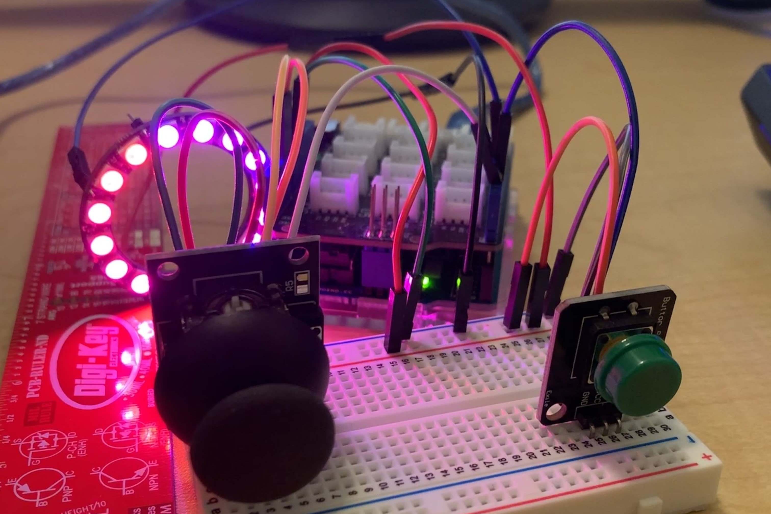
- Joystick Module: The core component of the project, the joystick module consists of two potentiometers and a button, enabling precise control and user input.
- Arduino Board: A microcontroller platform that serves as the central processing unit for the project. The Arduino board interprets the input from the joystick and executes the corresponding actions.
- Jumper Wires: These wires facilitate the electrical connections between the joystick module and the Arduino board, ensuring a secure and reliable interface.
- Breadboard (optional): While not mandatory, a breadboard can simplify the wiring process by providing a convenient platform for creating and testing the circuit before making permanent connections.
- USB Cable: Required for connecting the Arduino board to a computer for programming and power supply.
These components form the foundation for the joystick-to-Arduino project, enabling seamless integration and functionality. By gathering these items, you can proceed to the next steps of wiring the joystick to the Arduino, reading analog input, and programming the Arduino to interpret and respond to the joystick’s movements and button presses.
Wiring the Joystick to Arduino
Wiring the joystick to an Arduino involves establishing the necessary electrical connections to enable communication between the two components. The process begins by identifying the pins on the joystick module and the corresponding pins on the Arduino board.
Here’s a step-by-step guide to wiring the joystick to the Arduino:
- Connect the VCC Pin: Use a jumper wire to connect the VCC pin on the joystick module to the 5V pin on the Arduino board. This provides power to the joystick module.
- Link the GND Pin: Utilize another jumper wire to link the GND pin on the joystick module to any GND pin on the Arduino board, establishing a common ground reference.
- Wire the X-Axis and Y-Axis Analog Outputs: Connect the X-axis and Y-axis analog output pins on the joystick module to the analog input pins A0 and A1 on the Arduino board, respectively. These connections enable the Arduino to read the position of the joystick along each axis.
- Connect the Button Pin: If the joystick module includes a button, use a jumper wire to connect the button pin to a digital input pin on the Arduino board, such as pin 2 or 3. This allows the Arduino to detect button presses.
By following these wiring instructions, you establish the necessary connections to enable the Arduino to receive input from the joystick module. Once the wiring is complete, you can proceed to the next steps, which involve reading the analog input from the joystick, mapping the joystick input to desired output, and integrating additional functionalities, such as button presses, into your Arduino projects.
Reading Analog Input from the Joystick
Reading the analog input from the joystick is a crucial step in utilizing its positional data to control various aspects of a project. The two potentiometers in the joystick module produce analog voltage outputs that correspond to the position of the joystick along the x and y axes. To read this analog input and interpret the joystick’s movements, the Arduino employs its analog-to-digital converter (ADC) to convert the voltage levels into digital values that can be processed by the microcontroller.
Here’s how to read the analog input from the joystick using the Arduino:
- Initialize the Analog Pins: In the Arduino sketch, use the
analogRead()function to read the analog voltage values from the X-axis and Y-axis of the joystick, connected to the analog input pins A0 and A1, respectively. - Store the Analog Readings: Capture the analog readings obtained from the joystick’s potentiometers in variables within the Arduino code. These readings represent the position of the joystick along each axis and range from 0 to 1023.
- Map the Analog Values: If necessary, map the analog readings to the desired output range using the
map()function in the Arduino sketch. This step allows you to adapt the joystick’s input to control servos, motors, or other components within specific ranges. - Utilize the Analog Data: Once the analog input has been read and processed, you can use the obtained values to control the behavior of connected devices or trigger specific actions based on the joystick’s movements.
By effectively reading the analog input from the joystick, you gain the ability to harness its positional data for diverse applications, ranging from controlling the movement of robotic systems to steering virtual objects in interactive simulations. This foundational understanding sets the stage for developing innovative projects that leverage the precision and versatility of the joystick’s analog input.
Mapping Joystick Input to Output
Mapping the input from the joystick to the desired output range is a pivotal aspect of utilizing the joystick’s positional data to control external devices or processes. The analog voltage outputs from the joystick’s potentiometers, representing the x and y axes positions, need to be translated into suitable values that can effectively drive the behavior of connected components.
Here’s how you can map the joystick input to the desired output using the Arduino:
- Understand the Output Range: Determine the range of values required for the specific application. For instance, if the joystick is used to control the position of a servo motor, the output range should align with the servo’s angle requirements (typically 0 to 180 degrees).
- Use the Map Function: In the Arduino sketch, utilize the
map()function to scale the analog input values from the joystick to the desired output range. This function allows you to reassign the input values to a new range, ensuring compatibility with the connected devices or systems. - Apply Conditional Logic (Optional): Depending on the project’s complexity, you may incorporate conditional statements or additional logic to refine the mapped output values. This can involve adjusting the output based on specific thresholds, calibrating the response to the joystick’s movements, or implementing dynamic behaviors based on the input.
- Test and Refine: After mapping the joystick input to the desired output, it’s essential to test the functionality and refine the mapping as needed. Iterative testing and adjustments can fine-tune the relationship between the joystick input and the resulting output, ensuring precise and intuitive control.
By effectively mapping the joystick input to the desired output range, you empower the Arduino to translate the user’s physical input into meaningful actions, whether it’s controlling the motion of robotic arms, directing the movement of remote-controlled vehicles, or influencing visual elements in interactive installations. This process forms the bridge between the user’s manipulation of the joystick and the tangible effects produced by the connected devices, fostering a seamless and responsive user experience.
Adding a Button to the Joystick Circuit
Integrating a button into the joystick circuit enhances the user interaction and expands the range of input possibilities for Arduino projects. The button, when pressed, provides a digital input that can trigger specific actions, transitions, or states within the project. Incorporating this additional input element complements the joystick’s analog controls, offering a comprehensive interface for user engagement.
Here’s a guide to adding a button to the joystick circuit:
- Identify the Button Pin: Determine the pin on the joystick module that corresponds to the button. This pin serves as the connection point for integrating the button’s digital input with the Arduino.
- Establish the Connection: Use a jumper wire to connect the button pin on the joystick module to a digital input pin on the Arduino board, such as pin 2 or 3. This connection allows the Arduino to detect the state of the button, whether it’s pressed or released.
- Implement Pull-up Resistor (Optional): To ensure reliable button input readings, consider incorporating a pull-up resistor in the circuit. This resistor helps maintain a defined voltage level when the button is not pressed, preventing floating or ambiguous readings.
- Configure the Arduino Sketch: Within the Arduino sketch, set up the digital input pin connected to the button as an input with the appropriate configuration, such as enabling the internal pull-up resistor if an external one is not used.
- Implement Button Functionality: Define the behavior or actions triggered by the button press in the Arduino code. This can encompass activating specific routines, toggling modes, initiating calibration processes, or influencing the overall behavior of the project based on the button’s state changes.
By integrating a button into the joystick circuit, you introduce a versatile input mechanism that can be utilized for user-initiated events, mode switching, menu navigation, and various interactive functionalities. This expansion of input capabilities enriches the user experience and broadens the creative potential of Arduino projects, enabling dynamic and responsive interactions with the connected systems or applications.
Writing Code for Joystick Input
Creating the code to interpret and respond to the input from the joystick is a fundamental aspect of integrating the joystick with an Arduino-based project. The code enables the Arduino to read the analog input from the joystick’s potentiometers, process the input values, map them to the desired output range, and incorporate additional functionalities, such as responding to button presses. This programming phase forms the intelligence behind the interaction with the joystick, translating physical movements and button actions into meaningful control signals for connected devices or applications.
Here’s a breakdown of the essential steps for writing code to handle joystick input:
- Initialize Analog Input Reading: Begin the code by using the
analogRead()function to capture the analog voltage values from the X-axis and Y-axis of the joystick, connected to the analog input pins A0 and A1, respectively. Store these readings in variables for further processing. - Map Analog Values to Output Range: Utilize the
map()function to scale the analog input values to the desired output range, aligning them with the requirements of the connected components or systems. This step ensures that the joystick’s movements correspond to meaningful and actionable control signals. - Read Button State (If Applicable): If a button is integrated into the joystick circuit, include code to read the state of the button using the designated digital input pin. Detecting button presses and releases allows the Arduino to respond to user-initiated events.
- Incorporate Conditional Logic and Control Structures: Implement conditional statements, loops, and control structures to define the behavior of the project based on the joystick input and button state. This can involve adjusting the output, triggering specific actions, or dynamically responding to user interactions.
- Test and Refine the Code: After writing the initial code, conduct thorough testing to ensure the intended behavior aligns with the joystick input. Iterate on the code as needed to refine the responsiveness, accuracy, and overall performance of the joystick-controlled functionalities.
By crafting the code for joystick input, you empower the Arduino to interpret the user’s manipulations of the joystick and button, translating them into actionable commands that drive the behavior of connected devices or applications. This programming endeavor is pivotal in realizing the envisioned interactions and functionalities enabled by the joystick, fostering engaging and responsive user experiences within Arduino projects.
Testing the Joystick with Arduino
After wiring the joystick, writing the code, and integrating additional components, it’s crucial to conduct comprehensive testing to ensure the seamless functionality of the joystick within the Arduino project. Testing serves as a validation step, allowing you to verify the responsiveness, accuracy, and reliability of the joystick’s input and its impact on the connected devices or applications.
Here’s a guide to effectively testing the joystick with Arduino:
- Verify Analog Input Reading: Begin by confirming that the Arduino accurately reads the analog input from the joystick’s potentiometers. Move the joystick along both axes and observe the corresponding changes in the analog values. Ensure that the readings align with the physical movements of the joystick.
- Evaluate Mapped Output: Assess the mapped output values to ascertain that they fall within the expected range and effectively control the behavior of connected components, such as servos, motors, or visual displays. Verify that the mapped values accurately reflect the intended response to the joystick’s movements.
- Test Button Functionality: If a button is incorporated into the joystick circuit, test its functionality by pressing and releasing the button while monitoring the Arduino’s response. Validate that the button’s state changes trigger the intended actions or transitions within the project.
- Iterate on Code and Wiring: If discrepancies or unexpected behaviors arise during testing, iterate on the code and wiring to address any issues. Refine the code to enhance the responsiveness and accuracy of the joystick-controlled functionalities, and ensure the integrity of the electrical connections.
- Implement Real-World Scenarios: Integrate the joystick-controlled functionalities into real-world scenarios relevant to the project’s application. This can involve simulating the intended use case, such as controlling the movement of a robotic arm, navigating a virtual environment, or influencing interactive art installations, to validate the practicality and effectiveness of the joystick’s input.
Thorough testing of the joystick with Arduino not only validates the successful integration of the joystick within the project but also provides insights into optimizing the user experience, refining the code, and addressing any technical challenges. By rigorously testing the joystick’s functionalities, you ensure that it delivers the intended control and interaction capabilities, ultimately enhancing the overall quality and reliability of the Arduino project.