
XLR Connector Overview
Understanding the XLR Connector: A Comprehensive Guide
When it comes to audio connectivity, the XLR connector stands as a stalwart, known for its robustness and reliability. Originally developed by James Cannon in the mid-20th century, the XLR connector has become a ubiquitous feature in professional audio equipment, finding extensive use in microphones, amplifiers, and other audio devices.
The XLR connector is renowned for its three-pin design, which ensures secure and balanced connections, effectively minimizing interference and noise. This makes it the preferred choice in live sound reinforcement, studio recording, and various audio applications where clarity and fidelity are paramount.
One of the distinguishing features of the XLR connector is its locking mechanism, which provides a secure connection, preventing accidental disconnection during performances or recording sessions. This feature adds to its appeal in professional settings, where uninterrupted audio signals are crucial.
Moreover, the XLR connector is designed to facilitate the transmission of both audio and control signals, making it versatile and adaptable to a wide range of applications. Whether it’s conveying phantom power to microphones or transmitting line-level signals between audio components, the XLR connector proves its mettle in diverse scenarios.
With its robust construction and ability to carry balanced audio signals over long distances without signal degradation, the XLR connector has earned its reputation as an industry standard, embodying the pinnacle of professional audio connectivity.
Types of XLR Connectors
Exploring the Variants of XLR Connectors
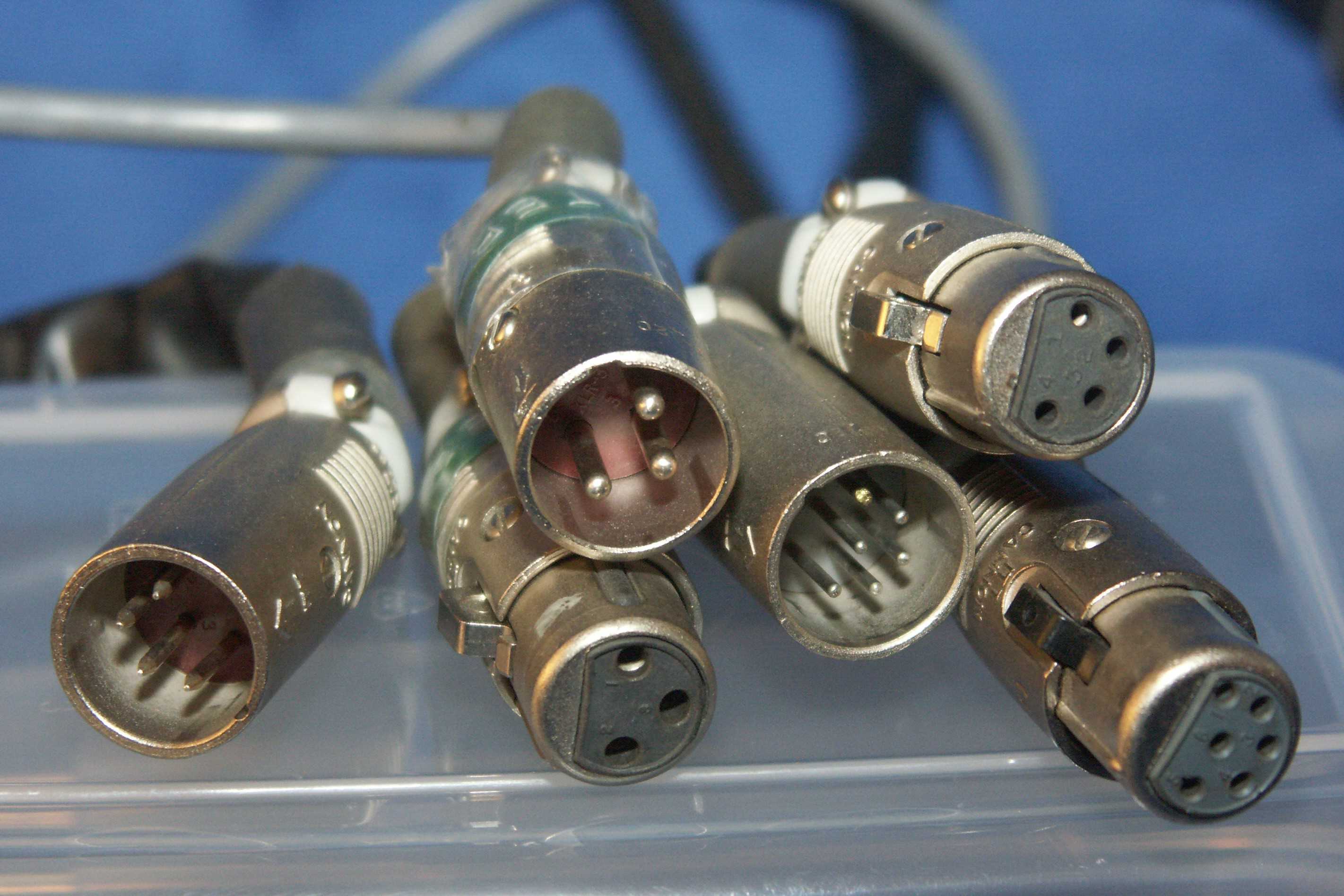
Within the realm of audio connectivity, XLR connectors manifest in various configurations, each tailored to specific applications and requirements. Understanding the distinct types of XLR connectors is essential for selecting the appropriate variant to suit diverse audio setups. Here are the primary types:
- XLR-3: The standard XLR connector, featuring three pins, is commonly utilized in balanced audio applications. It is prevalent in microphones, amplifiers, and audio interfaces, offering reliable signal transmission and noise rejection.
- XLR-5: This variant incorporates five pins and is often employed in lighting control systems and DMX (Digital Multiplex) applications. The additional pins enable the transmission of control signals alongside audio, expanding its utility beyond traditional audio connections.
- XLR-4: With four pins, this XLR configuration is frequently utilized in intercom systems and certain types of professional headphones. Its design allows for the transmission of audio signals along with a separate communication channel, enhancing its functionality in specific audio setups.
- XLR-6: Featuring six pins, this XLR variant is utilized in specific industrial and medical equipment, where the additional pins accommodate specialized signal requirements, such as power, data, or control signals, alongside audio transmission.
Each type of XLR connector is engineered to meet the demands of distinct audio and control signal applications, underscoring the versatility and adaptability of the XLR standard. Understanding the nuances of these variants empowers audio professionals to make informed decisions regarding connector selection, ensuring seamless and reliable signal transmission in diverse audio environments.
Pin Configurations
Deciphering the Pin Configurations of XLR Connectors
Understanding the pin configurations of XLR connectors is fundamental to harnessing their full potential in audio and control signal applications. The arrangement of pins within an XLR connector determines the functionality and compatibility with various devices and systems. Here are the standard pin configurations found in XLR connectors:
- Pin 1 (Ground): Serving as the ground connection, this pin ensures proper shielding and grounding of the audio signal, minimizing the risk of interference and noise contamination.
- Pin 2 (Hot/Send): Often designated as the “hot” or “send” pin, it carries the positive phase or signal of the balanced audio transmission, playing a pivotal role in maintaining signal integrity.
- Pin 3 (Cold/Return): Also known as the “cold” or “return” pin, it complements Pin 2 by transmitting the inverted phase or signal, contributing to the balanced audio transmission and facilitating noise cancellation at the receiving end.
These pin configurations align with the balanced audio transmission scheme, essential for minimizing electromagnetic interference and preserving signal quality over extended cable runs. Additionally, the pin configurations of XLR connectors may vary in multi-pin variants, accommodating additional functionalities such as control signals, data transmission, or power delivery, depending on the specific application requirements.
Moreover, the standardized pin configurations of XLR connectors enable seamless interoperability among audio devices and systems, fostering a universal approach to audio connectivity. Whether it’s linking microphones to mixing consoles, interfacing with amplifiers, or integrating lighting control systems, the consistent pin layouts of XLR connectors streamline the setup and operation of audio and control signal networks.
By comprehending the significance of pin configurations in XLR connectors, audio professionals can optimize signal flow, ensure compatibility across equipment, and harness the full potential of these robust and reliable connectors in diverse audio and control signal environments.
Wiring XLR Connectors
Mastering the Art of Wiring XLR Connectors
Properly wiring XLR connectors is a foundational skill for audio professionals, as it ensures seamless signal transmission and connectivity in various audio setups. Whether it’s configuring microphones, patch panels, or audio interfaces, understanding the wiring process for XLR connectors is essential. Here’s a comprehensive guide to wiring XLR connectors:
- Identifying Pins: Before commencing the wiring process, it’s crucial to identify the pin assignments of the XLR connector. Typically, Pin 1 is designated for ground, Pin 2 for the positive phase or “hot” signal, and Pin 3 for the negative phase or “cold” signal in balanced audio applications.
- Stripping and Preparing Cables: Begin by carefully stripping the outer insulation of the audio cable to expose the inner conductors. Ensure that the conductors are neatly twisted and free from any frayed ends or damage, as this directly impacts signal integrity.
- Soldering Connections: With the cables prepared, proceed to solder the conductors to their respective pins on the XLR connector. The positive phase conductor connects to Pin 2, the negative phase conductor to Pin 3, and the cable shield or ground conductor to Pin 1. Precision and attention to detail are crucial during the soldering process to avoid shorts and ensure reliable connections.
- Securing the Connector: Once the soldering is complete, carefully secure the XLR connector, ensuring that the internal connections remain intact and insulated. The connector’s strain relief feature should be utilized to prevent cable tension from affecting the soldered connections.
This meticulous approach to wiring XLR connectors guarantees robust and enduring connections, vital for maintaining signal integrity and minimizing the risk of signal loss or interference. Additionally, adhering to industry best practices and standards for wiring XLR connectors is imperative for ensuring compatibility and interoperability across audio equipment and systems.
By mastering the art of wiring XLR connectors, audio professionals can confidently configure audio interfaces, stage boxes, and various audio components, fostering seamless signal flow and reliability in live sound reinforcement, studio recording, and other audio applications.
Soldering XLR Connectors
The Craft of Soldering XLR Connectors: Ensuring Reliable Connections
Soldering XLR connectors is a critical aspect of audio equipment installation and maintenance, requiring precision and attention to detail to achieve durable and reliable connections. The soldering process not only establishes electrical continuity but also contributes to the overall integrity of the audio signal path. Here’s a step-by-step guide to soldering XLR connectors:
- Preparation: Begin by gathering the necessary tools, including a soldering iron, solder, wire strippers, and heat shrink tubing. Ensure that the work area is well-ventilated and that safety precautions, such as eye protection, are in place.
- Stripping and Tinning: Carefully strip the outer insulation of the audio cable to expose the inner conductors. Subsequently, “tin” the exposed conductors by applying a small amount of solder to each conductor, ensuring they are uniformly coated and free from frayed ends or stray wires.
- Connector Preparation: Inspect the XLR connector to verify the correct pin assignments. Prepare the connector by loosening the strain relief and disassembling the housing to access the solder cups or terminals for each pin.
- Soldering Process: With the prepared cable and connector, carefully solder the tinned conductors to their corresponding pins on the XLR connector. The positive phase conductor connects to Pin 2, the negative phase conductor to Pin 3, and the cable shield or ground conductor to Pin 1. Apply the soldering iron briefly to the solder cup, ensuring the solder flows evenly and forms a secure bond with the conductor.
- Insulation and Strain Relief: Once the connections are soldered, insulate each conductor and its respective pin with heat shrink tubing, providing an additional layer of protection and strain relief. Reassemble the connector housing, ensuring the strain relief is secured to prevent cable tension from affecting the soldered connections.
By meticulously following these steps, audio professionals can execute the soldering process with precision, resulting in robust and enduring connections within XLR connectors. Furthermore, adhering to industry standards and best practices for soldering XLR connectors is essential for maintaining signal integrity and ensuring the longevity of audio installations and equipment.
The craft of soldering XLR connectors embodies the commitment to excellence in audio connectivity, empowering professionals to establish reliable signal paths and uphold the fidelity of audio transmissions across diverse applications and environments.
Testing XLR Connections
Ensuring Seamless Signal Integrity: The Importance of Testing XLR Connections
Upon completing the wiring and soldering of XLR connectors, thorough testing is imperative to validate the integrity of the connections and ensure optimal signal flow. Testing XLR connections not only verifies the accuracy of the wiring and soldering processes but also safeguards against potential signal disruptions and performance issues. Here’s a comprehensive approach to testing XLR connections:
- Visual Inspection: Begin by visually inspecting the soldered connections and wiring within the XLR connectors. Ensure that the conductors are securely soldered to the respective pins, with no exposed wires or solder bridges that could lead to short circuits or signal interference.
- Continuity Testing: Employ a multimeter set to the continuity or resistance mode to verify the electrical continuity of each conductor within the XLR connector. By probing the soldered connections and cable conductors, any breaks or irregularities in the electrical path can be identified, allowing for timely rectification.
- Signal Path Testing: Utilize a signal generator and oscilloscope or audio analyzer to inject and trace test signals through the XLR connections. This comprehensive testing method enables the assessment of signal fidelity, phase coherence, and the absence of noise or distortion within the audio path.
- Cable Testing: If applicable, conduct cable testing to assess the overall performance and integrity of the entire XLR cable assembly. This includes evaluating the cable’s shielding effectiveness, impedance characteristics, and signal transmission capabilities, ensuring it meets the required specifications for reliable audio connectivity.
Thorough testing of XLR connections serves as a critical quality assurance measure, validating the efficacy of the wiring and soldering processes while mitigating the risk of signal anomalies and performance degradation. By meticulously examining the connections and subjecting them to rigorous testing, audio professionals can instill confidence in the reliability and fidelity of the XLR connections within their audio systems.
Additionally, documenting the testing procedures and results contributes to a comprehensive record of the installation or maintenance process, providing valuable insights for future troubleshooting and system optimization. Ultimately, the commitment to thorough testing ensures that XLR connections uphold the highest standards of signal integrity and performance across diverse audio applications.