
What is PCI?
Peripheral Component Interconnect (PCI) is a computer bus standard that establishes a connection between the peripheral devices and the motherboard of a computer. It acts as an interface for various hardware components such as network cards, sound cards, graphics cards, and expansion cards.
The primary purpose of PCI is to facilitate communication and data transfer between the computer’s central processing unit (CPU) and peripheral devices. It provides a standardized way for these devices to exchange data and share resources, ensuring compatibility across different hardware configurations.
PCI is widely regarded as a universal bus interface due to its widespread adoption in both desktop and server systems. It offers high-speed data transfer rates and supports multiple devices simultaneously. As a result, it has become an integral part of modern computer architectures.
One of the key advantages of PCI is its plug-and-play capability, which allows devices to be easily installed and recognized by the operating system without requiring manual configuration. This makes it convenient for users to add or upgrade peripheral devices, enhancing the overall functionality and performance of their computers.
Furthermore, PCI offers a significant performance improvement over older bus standards like ISA (Industry Standard Architecture). With its faster data transfer rates and improved bus mastering capabilities, PCI can handle demanding tasks and support high-bandwidth applications.
PCI has undergone several advancements and revisions since its inception, leading to the development of newer versions such as PCI-X and PCI Express (PCIe). These iterations offer even faster data transfer speeds and are optimized for specific types of devices.
History of PCI
The history of PCI dates back to the early 1990s when the need for a faster and more efficient bus interface for computers became apparent. At that time, the prevalent bus standard was ISA (Industry Standard Architecture), which had limitations in terms of speed and bandwidth.
In 1992, Intel Corporation introduced the Peripheral Component Interconnect (PCI) specification as a replacement for ISA. The goal was to create a standardized bus architecture that could accommodate the increasing demands of emerging technologies.
The original PCI specification, known as PCI 1.0, was a 32-bit bus that ran at 33 MHz. It offered a substantial improvement in performance over ISA, allowing for faster data transfer rates and improved system responsiveness.
As technology progressed, the need for higher bandwidth and more advanced features led to the development of subsequent versions of the PCI specification. PCI 2.0, introduced in 1993, increased the bus speed to 66 MHz, effectively doubling the data transfer rate.
In 1995, the PCI Special Interest Group (PCI-SIG) released the PCI 2.1 specification, which introduced the concept of the PCI bridge. This allowed multiple PCI buses to be interconnected, expanding the system’s ability to accommodate a larger number of devices.
The PCI 2.2 specification, released in 1998, included support for 64-bit addressing, enabling the use of more memory and enhancing system performance. It also introduced the concept of AGP (Accelerated Graphics Port), a high-performance bus specifically designed for graphics cards.
Subsequent versions of PCI, including PCI 2.3 and PCI 3.0, continued to refine and improve upon the original specification, offering faster bus speeds, increased bandwidth, and enhanced capabilities.
With the advancement of technology and the growing demand for higher speeds and more advanced features, PCI Express (PCIe) was introduced in 2004. PCIe represented a significant departure from the traditional PCI architecture, offering higher data transfer rates and improved scalability.
Today, PCIe is the predominant bus interface for modern computers, while PCI continues to be used in legacy systems or for specific peripheral devices that do not require the advanced features offered by PCIe.
PCI Architecture
The PCI architecture comprises several fundamental components that work together to establish communication and data transfer between the CPU and peripheral devices.
At the center of the PCI architecture is the PCI host bridge, which serves as the interface between the CPU and the PCI bus. It manages the flow of data between the CPU, the system memory, and the PCI devices.
The PCI bus consists of a set of electrical lines that transmit control and data signals. The bus allows multiple devices to be connected and communicate with each other simultaneously.
Each device connected to the PCI bus is assigned a unique identification number known as a PCI device number. This number helps in identifying and accessing the specific device on the bus.
PCI supports two types of transactions: memory-mapped I/O (MMIO) and input/output (I/O) operations. In MMIO transactions, the device’s memory space is physically mapped to the system memory, allowing direct access to the device’s registers and data. In I/O operations, the CPU communicates with I/O devices using a specific set of input and output instructions.
PCI follows a decentralized bus arbitration mechanism, where devices can arbitrate for the bus ownership when they need to transfer data. This ensures fair access to the bus and prevents conflicts between devices.
To further expand the system’s capabilities, PCI bridges are used. A PCI bridge acts as an intermediary device, connecting two or more PCI buses together. This allows for the expansion of the system by adding more PCI slots or connecting peripheral devices that require a separate bus.
The PCI configuration space is a reserved area of memory that contains information about each PCI device connected to the bus. This space includes parameters such as device identification, vendor ID, device class, and resource requirements. The operating system uses this information to identify and configure the devices during system startup.
With the introduction of PCI Express (PCIe), the architecture has evolved further to accommodate faster data transfer rates and additional features. PCIe uses a point-to-point topology, where each device is connected to the CPU through dedicated links, providing higher bandwidth and improved scalability.
PCI Connectors
PCI connectors play a crucial role in ensuring a physical connection between the PCI bus and the peripheral devices. These connectors come in different form factors and have evolved over time to accommodate the changing needs of the industry.
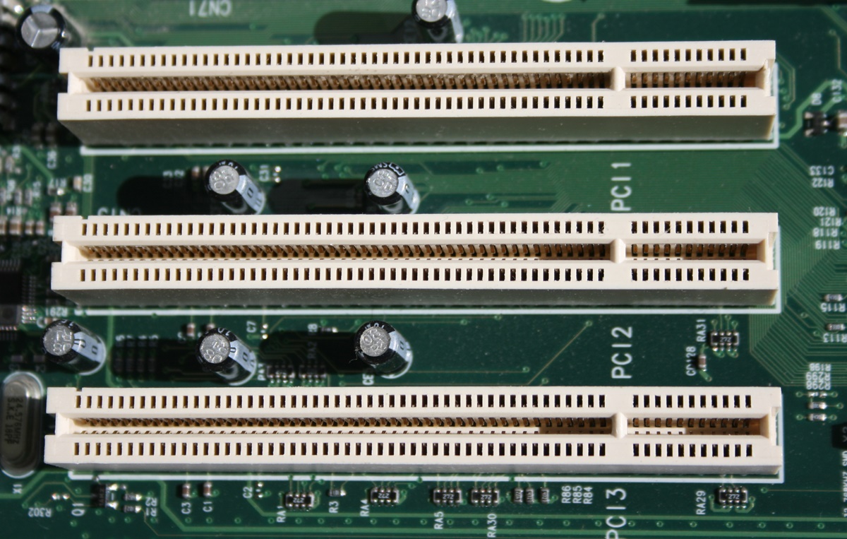
The most common type of PCI connector is the PCI slot. PCI slots are found on the motherboard of a computer and serve as the interface for installing expansion cards and other peripheral devices. Each PCI slot consists of a plastic or metal slot with multiple electrical contacts that establish a connection with the device when inserted.
PCI slots have undergone several iterations to keep up with advancements in technology. The original PCI slots, commonly known as PCI-33 slots, were 32-bit slots that operated at a bus speed of 33 MHz. These slots are characterized by their white color and relatively shorter length.
As technology progressed, faster and more advanced versions of PCI were introduced. PCI-X (PCI Extended) and PCI Express (PCIe) slots became popular choices for high-speed data transfer and improved performance.
PCI-X slots have a similar physical appearance to standard PCI slots but with additional notches to prevent the insertion of incompatible cards. These slots can support higher bus speeds, ranging from 66 MHz to 133 MHz, and offer increased bandwidth for demanding applications.
PCIe slots, on the other hand, have a different physical design and offer even higher data transfer rates. PCIe slots are characterized by their smaller and longer size, with various configurations such as PCIe x1, PCIe x4, PCIe x8, and PCIe x16. These configurations denote the number of individual data lanes available, with each lane capable of transmitting data simultaneously.
PCIe slots also have a locking mechanism, such as a latch or retention clip, to ensure secure insertion and retention of the card. This feature provides better stability and prevents accidental removal of the card during operation.
Additionally, PCIe slots are backward compatible, meaning they can support older PCI and PCI-X cards with the use of adapters or passive riser cards.
Overall, PCI connectors have evolved to accommodate faster data transfer rates, improved performance, and enhanced compatibility. The choice of connector depends on the specific requirements of the peripheral device and the motherboard’s compatibility.
PCI Versions
The Peripheral Component Interconnect (PCI) standard has gone through several iterations and revisions to keep up with the evolving demands of computer systems. Each version of PCI introduces improvements in terms of data transfer rates, bus speeds, and enhanced features. Here are the notable versions of PCI:
PCI 1.0
Introduced in 1992, PCI 1.0 was the first version of the standard. It featured a 32-bit bus and operated at a bus speed of 33 MHz. PCI 1.0 provided a significant performance boost over the older ISA standard and quickly gained popularity in early computer systems.
PCI 2.0
Released in 1993, PCI 2.0 improved upon the original specification by doubling the bus speed to 66 MHz while maintaining backward compatibility. This increased the data transfer rate to 133 MB/s and allowed for improved performance in high-bandwidth applications.
PCI 2.1
In 1995, PCI 2.1 was introduced, which included the addition of the PCI bridge mechanism. The bridge enabled multiple PCI buses to be interconnected, expanding the system’s ability to support a larger number of devices. This version also introduced support for plug-and-play functionality, simplifying the installation and configuration of PCI devices.
PCI 2.2
With PCI 2.2, released in 1998, support for 64-bit addressing was introduced, allowing for larger memory installations and improved system performance. It also included the introduction of the Accelerated Graphics Port (AGP) specification, specifically designed to provide high-performance graphics capabilities.
PCI 2.3
PCI 2.3, released in 2002, added incremental improvements to the standard. It refined the electrical specifications for better signal integrity and introduced support for the Universal Serial Bus (USB) and increased power management capabilities.
PCI 3.0
PCI 3.0, released in 2004, increased the bus speed to 133 MHz, doubling the data transfer rate again to 266 MB/s. This version also implemented improvements in electrical and signal specifications, providing greater reliability and performance.
It’s important to note that PCI versions are backward compatible, meaning newer devices can be used with older PCI slots, albeit at reduced performance. Additionally, the introduction of PCI Express (PCIe) brought a different architecture and additional versions, which became the standard for modern computer systems.
PCI Bus Arbitration
PCI bus arbitration is a critical mechanism that ensures fair access to the PCI bus when multiple devices are competing for its usage. The arbitration process determines which device on the bus gets to transmit data at any given time.
Within the PCI architecture, two different mechanisms handle bus arbitration: centralized and decentralized arbitration.
Centralized Arbitration
In centralized arbitration, a single device, known as the bus master, controls the bus and grants access to other devices. This device performs the arbitration process by making requests and granting bus ownership to other devices as needed. Centralized arbitration is commonly used in multi-master PCI systems, where multiple devices can act as bus controllers.
Decentralized Arbitration
Decentralized arbitration, also known as distributed arbitration, is a more commonly used mechanism in PCI systems. Within this method, each device on the PCI bus has equal priority to request bus ownership and initiate bus transactions.
When a device on the bus wants to transmit data, it asserts the bus request signal (BR#) to indicate its intent to use the bus. If the bus is idle, the device becomes the bus master and is granted immediate access to transmit data. However, if multiple devices assert the bus request signal simultaneously, the PCI arbiter resolves the contention by assigning the bus to a single device based on predefined priority rules.
The priority rules define a hierarchy among devices, with higher priority devices given precedence over lower priority ones. This ensures that critical devices, such as the CPU or high-priority input/output devices, are granted timely access to the bus and maintain system functionality and responsiveness.
The PCI arbiter resolves the bus arbitration process using a combination of fixed and rotating priority schemes. The fixed priority scheme assigns a constant priority level to specific devices or device types, while the rotating priority scheme cyclically changes the priority of each device, ensuring fair access to the bus over time.
Overall, PCI bus arbitration ensures efficient and fair utilization of the bus bandwidth, enabling multiple devices to share the bus resources effectively. By managing the contention between devices, the arbitration mechanism allows for smooth and coordinated data transfer within a PCI system.
PCI Configuration Space
The PCI configuration space is a reserved area of memory in a PCI device that contains important information about the device’s characteristics, capabilities, and configuration settings. It provides a standardized format for the operating system to identify and configure the devices connected to the PCI bus.
Each device connected to the PCI bus has its own configuration space, which is accessible through a unique bus, device, and function number. The configuration space is typically 256 bytes in size, organized into a set of predefined registers.
These registers contain vital information about the device, such as the device and vendor IDs, device class, subsystem IDs, revision numbers, and interrupt routing capabilities. The device and vendor IDs are essential for the operating system to identify the device and load the appropriate device driver.
Additionally, the configuration space registers provide details regarding the device’s resource requirements, such as memory and I/O ranges, interrupt request (IRQ) lines, and bus mastering capabilities. These resources are crucial for the operating system to allocate and manage system resources efficiently.
The configuration space also includes a set of registers that allow the operating system to control and configure various aspects of the device. These registers provide control over device-specific features, such as power management settings, bus settings, clock frequencies, and other device-specific functionalities.
One important register in the configuration space is the Command register. This register allows the operating system to enable or disable specific functionalities of the device, such as memory mapping, bus mastering, and I/O operations. By configuring the Command register, the operating system can control the behavior and operation of the PCI device.
Access to the PCI configuration space is typically done through read and write operations initiated by the operating system or device drivers. The operating system uses software-based mechanisms, such as configuration space access APIs or device-specific drivers, to access and modify the configuration registers as required.
Understanding the PCI configuration space is crucial for effective device configuration, resource allocation, and compatibility management in a PCI system. The information contained within the configuration space provides the foundation for proper initialization, discovery, and utilization of PCI devices by the operating system.
PCI Type of Transactions
PCI transactions are the fundamental operations that occur between the central processing unit (CPU) and peripheral devices connected to the PCI bus. These transactions dictate how data is transferred and accessed within the PCI system. There are three types of transactions commonly used in the PCI architecture:
Memory-Mapped I/O (MMIO)
Memory-Mapped I/O (MMIO) transactions provide a mechanism for devices to directly access system memory as if it were their own memory space. When a device wants to read or write data, it uses memory addresses rather than specific input/output instructions.
In MMIO transactions, the operating system maps the device’s memory space into the system memory address space during initialization. This allows the device to read from or write to its registers and data just as if it was accessing its own memory.
MMIO transactions are commonly used for devices that require direct memory access, such as graphics cards and network adapters. The direct memory mapping enables faster data transfer and eliminates the need for intermediate buffer storage.
I/O Operations
I/O operations involve using specific input/output instructions to communicate between the CPU and devices. Devices use specific I/O addresses to read from or write to their ports, which are distinct from memory addresses.
I/O operations are typically used for devices that do not require high-speed data transfers or direct memory access, such as serial and parallel ports, keyboards, and mice. These devices interact with the CPU through dedicated input/output instructions, allowing for lower-latency access to these peripheral components.
Unlike MMIO transactions, I/O operations do not directly access system memory. Instead, they involve commands and data transfers between the CPU and the device’s specific I/O ports.
Configuration Transactions
Configuration transactions are specialized transactions used to read from and write to the PCI configuration space of a device. These transactions allow the operating system to identify and configure the devices connected to the PCI bus during system startup.
A device’s configuration space contains important information about its characteristics, capabilities, and resource requirements. Through configuration transactions, the CPU can access and modify the configuration registers to assign addresses, set parameters, and control the device’s behavior.
Configuration transactions occur through specific memory and I/O addresses, providing direct access to the registers within a device’s configuration space. These transactions are critical for device enumeration, resource allocation, and proper initialization of PCI devices.
By supporting different types of transactions, the PCI architecture provides flexibility and efficiency in data transfer and device communication. The ability to leverage memory-mapped I/O, I/O operations, and configuration transactions ensures optimal performance and compatibility for various devices within the PCI system.
PCI Bridges
PCI bridges play a crucial role in expanding the connectivity and scalability of PCI-based systems. A bridge acts as an intermediary device that connects two or more PCI buses together, allowing for the seamless integration of additional peripheral devices.
PCI bridges facilitate the expansion of a system by enabling the addition of more PCI slots or providing connectivity to devices that require a separate PCI bus. They effectively extend the reach of the PCI architecture, allowing devices to communicate across multiple buses.
There are two main types of PCI bridges:
Primary Bridges
Primary bridges are the main bridges in a PCI system and are usually integrated into the computer’s motherboard. They connect the CPU’s primary PCI bus, also known as the host bus, to the secondary PCI buses that accommodate additional peripheral devices.
The primary bridge coordinates the flow of data between the CPU, the system memory, and the secondary buses. It acts as a central hub for data transfer, ensuring efficient communication between all connected devices.
Secondary Bridges
Secondary bridges, or PCI-to-PCI bridges, expand the capabilities of the primary bridge by connecting additional peripheral devices on secondary PCI buses. These bridges connect secondary buses to either the primary bridge or other secondary bridges in a cascaded manner.
Secondary bridges facilitate the expansion of the PCI system beyond the limitations of a single PCI bus, allowing for a larger number of devices to be connected. They enable the creation of complex and flexible PCI architectures by providing additional slots and supporting different bus configurations.
Each bridge, whether primary or secondary, maintains its own set of registers to control its operation and configuration. These registers handle functions such as address mapping, bus timing, and data transfer between the buses.
PCI bridges also play a crucial role in managing interrupts. They handle interrupt signals received from devices on the secondary buses and forward them to the primary bridge, which then routes them to the CPU for appropriate processing.
Overall, PCI bridges are essential components in expanding the connectivity and functionality of PCI-based systems. They provide the means to integrate additional devices, extend bus capacity, and create more versatile and scalable computer architectures.